
Combustion chamber sealing ring, and a combustion chamber including such a ring

a technology of combustion chamber and sealing ring, which is applied in the field of combustion chambers, can solve the problems of increasing the lifetime of the combustion chamber, and achieve the effect of finer calibration of the flow ra

Active Publication Date: 2006-01-24
SN DETUDE & DE CONSTR DE MOTEURS DAVIATION S N E C M A
View PDF19 Cites 44 Cited by
  • Summary
  • Abstract
  • Description
  • Claims
  • Application Information

AI Technical Summary

Benefits of technology

The present invention provides a sealing ring for a combustion chamber that allows a cooling air stream to flow in the zone where the combustion chamber is connected to the casing. This sealing ring is fixed to the end of the combustion chamber and reduces the area of the sealing ring that presses against the wall of the combustion chamber, increasing the lifetime of the combustion chamber. The sealing ring has a recess in its face facing the wall of the combustion chamber, allowing a stream of cooling air to flow. The sealing ring can be made out of a thermostructural composite material or metal alloy. The combustion chamber can also have perforations in the sealing ring connection zone, and a gasket can be used to obstruct any leakage outlet from the sealing ring. The leakage flow helps to cool the outer shroud of the high pressure nozzle and control the rate at which air enters into the combustion chamber. The invention also provides a combination of two rings for increased lifetime of the combustion chamber.

Problems solved by technology

This increases the lifetime of the combustion chamber.

Method used


Image

  • Combustion chamber sealing ring, and a combustion chamber including such a ring
  • Combustion chamber sealing ring, and a combustion chamber including such a ring
  • Combustion chamber sealing ring, and a combustion chamber including such a ring

Examples


Embodiment Construction

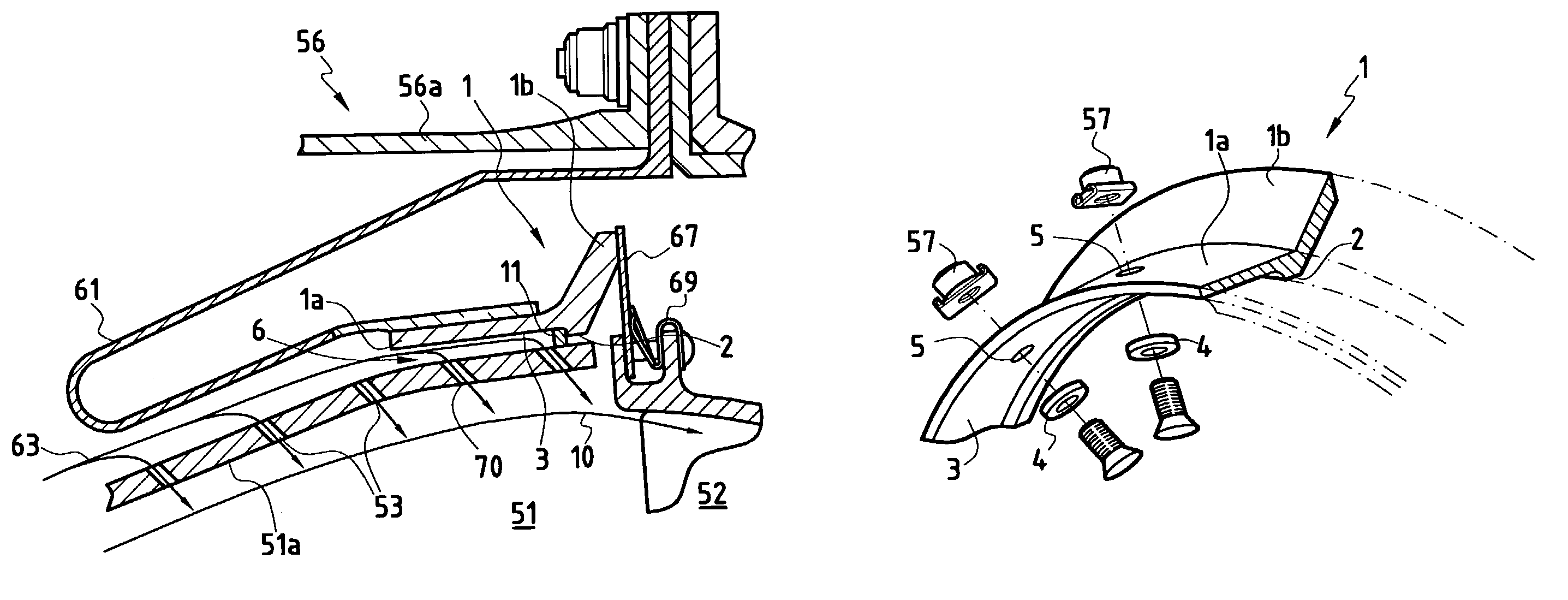
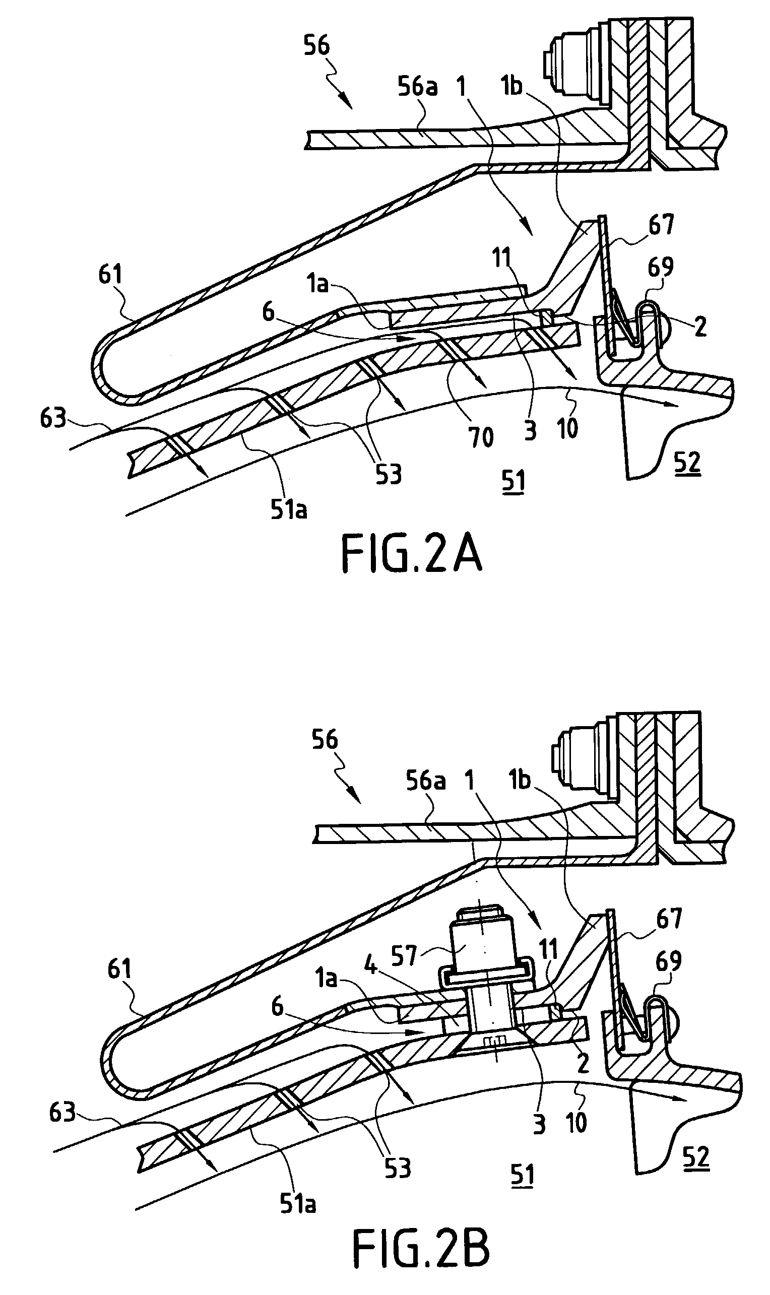
[0039]The present invention is described with reference to a ring for providing sealing between a combustion chamber and a nozzle. Nevertheless, the person skilled in the art will have no difficulty in applying the invention to a ring for connecting flexible connection tabs to the combustion chamber as described in French patent applications FR 01 / 07361 and FR 01 / 07363 in the name of the present Applicant. In general, the present invention applies to any type of ring which covers a portion of a wall of a structure that needs to be cooled by a flowing air stream.

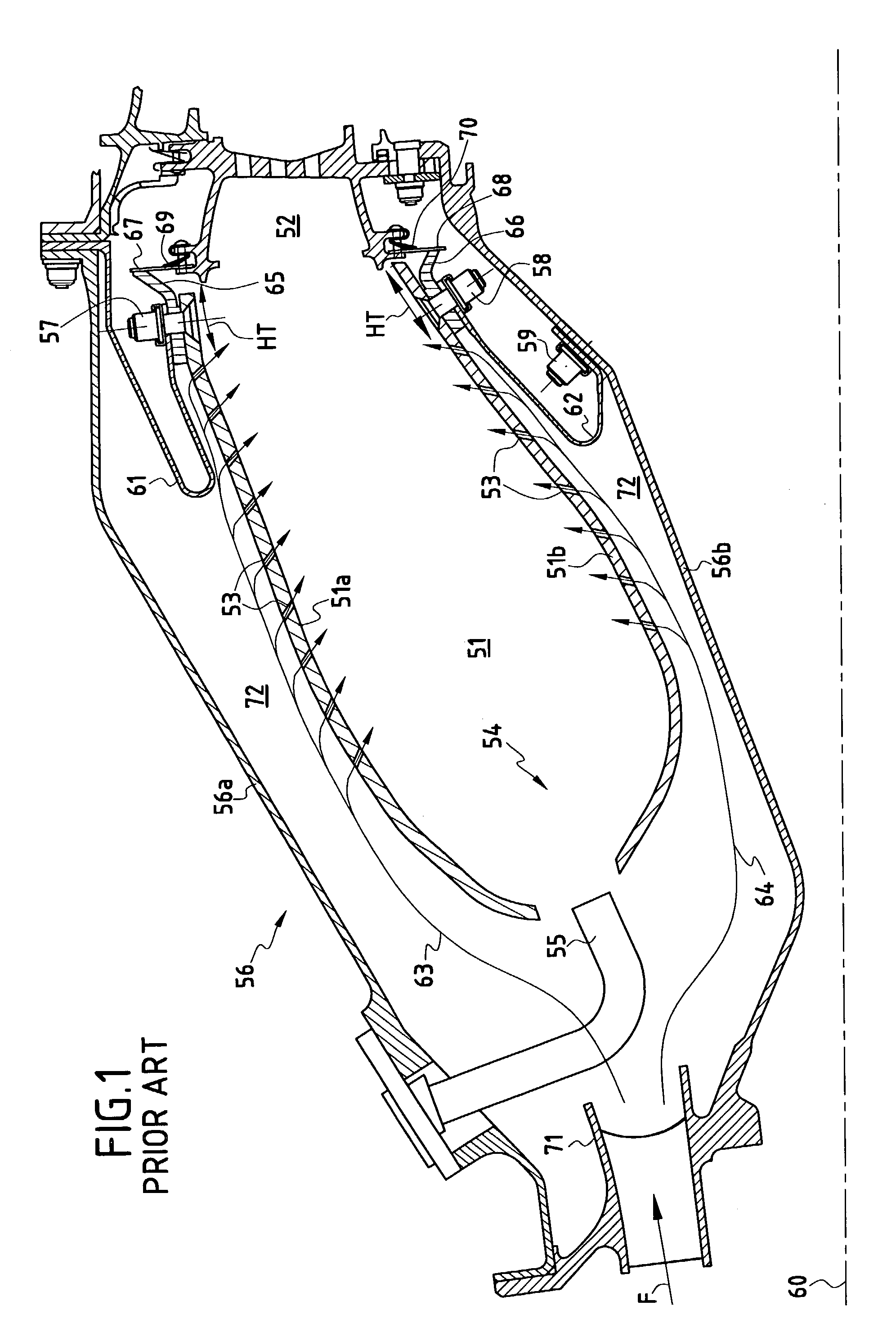
[0040]FIGS. 2A, 2B, and 3 show a sealing ring constituting a first embodiment of the invention. In FIG. 2, the elements of the combustion chamber and of the casing which remain unchanged are given the same reference symbols as those given in FIG. 1. In this first embodiment, the sealing ring 1 defines an annular structure comprising two portions: a sleeve 1a and a flange 1b. The sleeve 1a corresponds to the portion of the sea...


PUM


Abstract

The present invention provides a fixing or sealing ring for maximizing cooling at the end of a combustion chamber wall. For this purpose, the ring is constituted by a sleeve which is fixed around the end of a wall of the combustion chamber by means of a plurality of orifices for receiving fasteners or by means of any other system for connecting the ring to the wall. The sleeve includes at least one recess in its face facing the wall of the combustion chamber, thereby reducing the area of the sleeve that presses against the wall, and co-operating with said wall to form an open cavity in which a cooling air stream can flow.

Description

FIELD OF THE INVENTION[0001]The present invention relates to the field of combustion chambers, in particular in gas turbines. More particularly, the invention relates to cooling the walls of such combustion chambers between two shrouds.PRIOR ART[0002]FIG. 1 is an axial section view of the downstream portion of an aeroengine gas turbine which comprises, in conventional manner, a combustion chamber 51 disposed in a combustion chamber casing 56 in annular manner around the axis 60 of the engine.[0003]The combustion chamber 51 mainly comprises an outer wall 51a and an inner wall 51b mechanically linked respectively with the outer portion 56a and the inner portion 56b of the combustion chamber casing 56. More precisely, the outer wall 51a of the combustion chamber is connected to the outer portion 56a of the combustion chamber casing 56 by means of a plurality of flexible connection tabs 61 fixed on the outer wall 51a of the combustion chamber 51 by fasteners 57 of the nut-and-bolt type....

Claims


Application Information

Patent Timeline
Patent Type & Authority Patents(United States)
IPC IPC(8): F02C7/20F23R3/08F02C7/00F02C7/18F23R3/00F23R3/50F23R3/52F23R3/60
CPCF23R3/007F23R3/60F23R3/50F05B2230/606F23M2900/05004Y02T50/675F23R2900/03042Y02T50/67F01D9/02F16J15/08F23R3/16Y02T50/60
Inventor CONETE, ERICMIRAMBEAU, FRANCISHABAROU, GEORGESHERNANDEZ, DIDIERPIEUSSERGUES, CHRISTOPHE
Owner SN DETUDE & DE CONSTR DE MOTEURS DAVIATION S N E C M A
Learn More