Flat filter for venting gas in intravenous medical lines

Inactive Publication Date: 2006-01-24
IND BORLA
View PDF6 Cites 61 Cited by
  • Summary
  • Abstract
  • Description
  • Claims
  • Application Information

AI Technical Summary

Benefits of technology

[0010]An additional important advantage of the invention resides in the fact that, thanks to the presence of the collecting channel, in use air is released through the vent hole in continuous fashion, hence more efficiently than in known solutions with two separate holes. Moreover, if the inlet and the outlet of the case are both positioned at an end of the frontal plate, the

Problems solved by technology

There is also the complication due to t

Method used


Image

  • Flat filter for venting gas in intravenous medical lines
  • Flat filter for venting gas in intravenous medical lines
  • Flat filter for venting gas in intravenous medical lines

Examples


Embodiment Construction

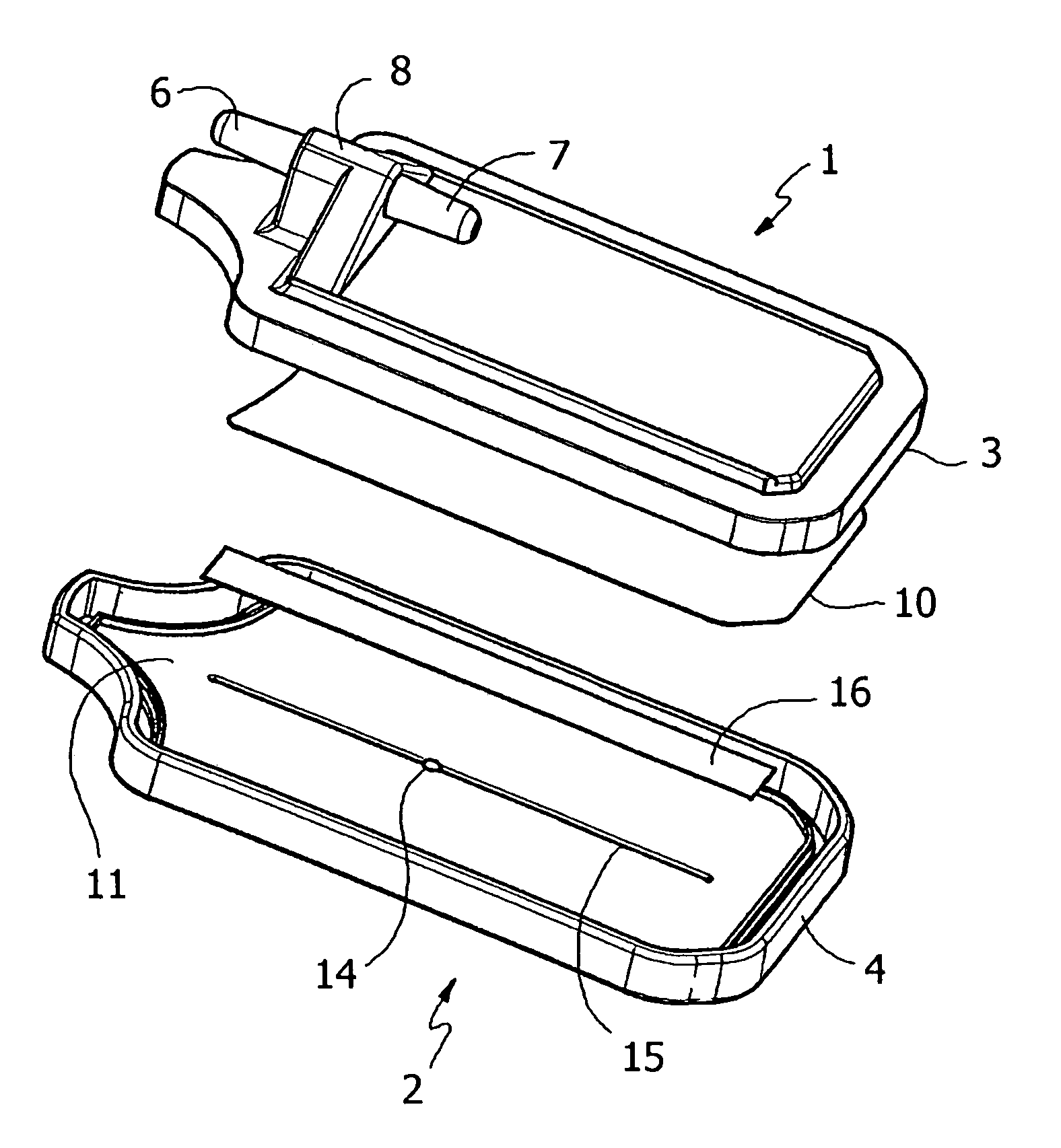
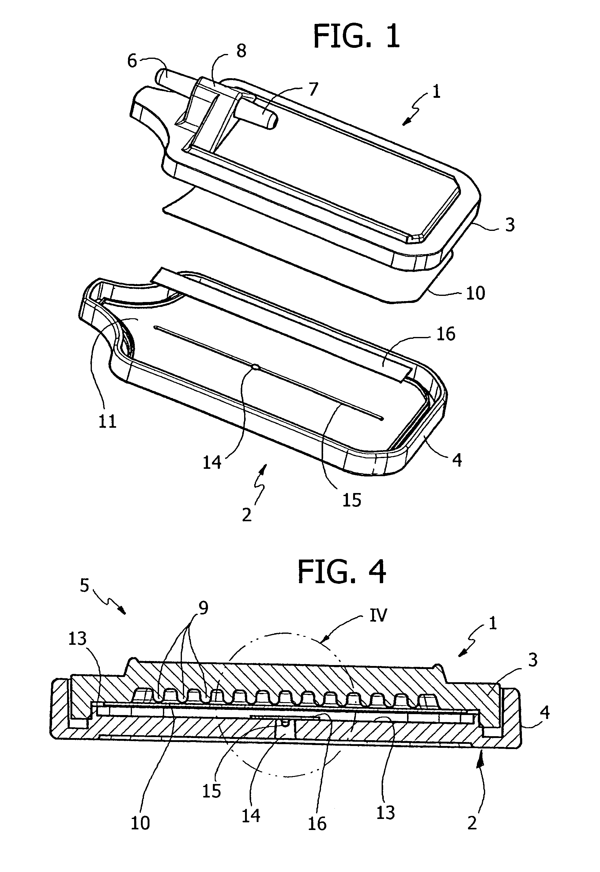
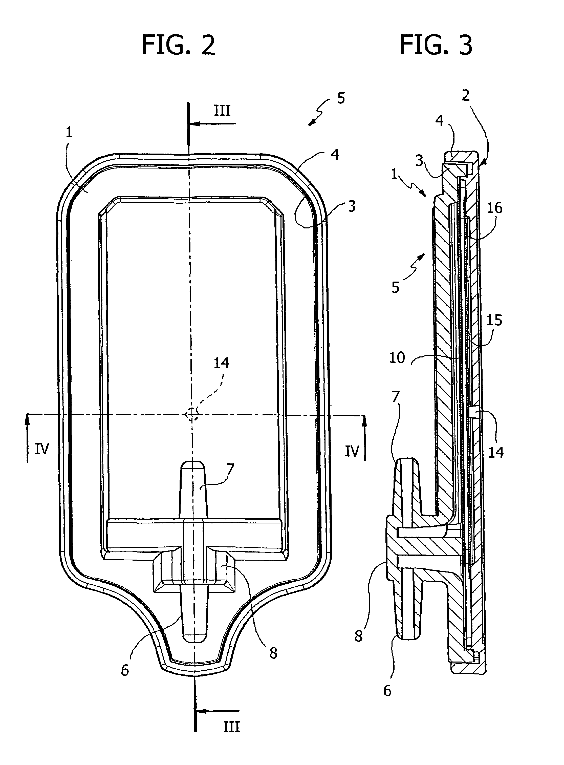
[0019]With reference to the drawings, a flat filter according to the invention, intended for use in an intravenous medical line, is formed by two superposed plates, respectively front plate 1 and dorsal plate 2, both made of normally transparent plastic material and mutually coupled in hermetic fashion along the respective peripheral edges 3, 4 in the manner shown in detail in FIGS. 2 and 3, for instance by means of ultrasonic welding, gluing or equivalent systems.

[0020]The two plates 1 and 2 thus define a case 5 through which the intravenous fluid is made to pass entering from a tubular inlet 6 and exiting from a tubular outlet 7. In the case of the illustrated example, the two tubular conduits 6, 7 project from opposite parts from an integral projection 8 formed at an end of the frontal plate 1, in substantially similar fashion to what is described and illustrated in the aforementioned document EP-A-1214955.

[0021]The inner wall 13 of the frontal plate 1 is formed with a series of ...


PUM

PropertyMeasurementUnit
Hydrophilicityaaaaaaaaaa

Abstract

Flat filter for venting gas in intravenous medical lines, comprising a case formed by a frontal plate and by a dorsal plate between which a hydrophilic filtering membrane is interposed. The dorsal plate has a single through hole for gas venting in communication with an elongated collecting channel formed on the inner surface of the dorsal plate and along which a hydrophobic membrane of complementary shape is applied.

Description

FIELD OF THE INVENTION[0001]The present invention relates to a flat filter for venting gas in intravenous medical lines.[0002]More in particular, the invention relates to such a flat filter of the type comprising a case having an inlet and an outlet and formed by a front plate and by a dorsal plate mutually superposed and coupled peripherally in hermetic fashion, a hydrophilic filtering membrane interposed between the two plate and in use traversed by the intravenous fluid entering the case through the inlet and exiting from the case through the outlet, and vent opening means with associated hydrophobic membrane means for the escape of the gas from the case.STATE OF THE PRIOR ART[0003]Such flat filters are known for example from the documents EP-A-0302722 in the name of Gelman, EP-A-0784988 in the name of Filtertek and EP-A-1214955 in the name of Industrie Borla S.p.A.[0004]In the document EP-A-0302722 the inlet and the outlet are positioned one on the frontal plate and the other on...

Claims


Application Information

Patent Timeline
IPC IPC(8): A61M1/00A61B19/00A61M5/00A61M5/165A61M5/36B01D19/00
CPCA61M5/165B01D19/0031A61M5/36
Inventor GUALA, GIANNI
Owner IND BORLA
Why Eureka
Try Eureka