Particulate filter for purifying exhaust gases of internal combustion engines comprising hot spot ceramic ignitors

a technology of ceramic ignitors and filter bodies, which is applied in the direction of filtration separation, auxillary pretreatment, separation processes, etc., can solve the problems of increasing the head loss due to the filter body, reducing the performance of the engine, and various techniques have been developed. , to achieve the effect of preventing the propagation of combustion, short response time and high dependence on engine operating conditions

Inactive Publication Date: 2006-01-24
SAINT GOBAIN CENT DE RES & DEVS & DETUD EUROEN
View PDF17 Cites 14 Cited by
  • Summary
  • Abstract
  • Description
  • Claims
  • Application Information

AI Technical Summary

Benefits of technology

[0019]Hot spot ceramic ignitors most importantly yield a system with a very short response time. Although glow plugs take from 10 to 40 seconds to reach a temperature of 1000° C., ceramic ignitors can reach the same temperature in only 3 to 6 seconds. This is crucial because if heating is not sufficiently fast the soot tends to be consumed rather than ignited; this produces a kind of barrier that prevents propagation of combustion. What is more, regeneration of the filter is commanded and usually initiated only under optimum engine operating conditions. The effectiveness of regeneration is highly dependent on engine operating conditions. A very short response time very considerably reduces the risk of a significant change in engine operating conditions between starting the regeneration process and the moment which the soot is actually ignited.
[0020]Tests have shown that the low power consumption of each ignitor means that several ignitors can be used simultaneously. The number of ignitors can be higher or lower depending on their characteristics and the type of filter in which they are used.
[0021]The small size of the ignitors means that they can be positioned very accurately. This can be of particular advantage in achieving good coverage of areas where it is known that regeneration is poor in conventional systems, usually at the periphery of the filter body. The compact size of these heat sources also means that they can be positioned as close as possible to the filter body; there can even be point contact between the hot spot of the ignitor and either the filter body or the soot deposited on its surface.

Problems solved by technology

After some time in use, soot accumulates in the filter body passages, in particular on the upstream face, which increases the head loss due to the filter body and therefore reduces the performance of the engine.
Various techniques have been developed but consume a great deal of energy and are very often difficult to control.
First of all, they are bulky, which makes it difficult to position them relative to the filter body. FIG. 2 of FR-A-2 771 449 shows clearly that it is not possible to place the heating means in direct contact with the soot and even less so with the core of the filter body.
Moreover, it is found that the presence of the heating means blocks access of the exhaust gases to a number of filter body passages, considerably reducing efficiency.
Also, a great deal of energy is consumed and the regeneration system has a mediocre response time because the temperature increases relatively slowly.
Other heating means, such as simple electrical elements, are unsuitable because the temperatures can reach more than 1000° C. in the filter during combustion of the soot, and few materials can be used under these temperature and oxidation conditions because the problem of rapid wear due to corrosion becomes very serious.

Method used


Image

  • Particulate filter for purifying exhaust gases of internal combustion engines comprising hot spot ceramic ignitors
  • Particulate filter for purifying exhaust gases of internal combustion engines comprising hot spot ceramic ignitors
  • Particulate filter for purifying exhaust gases of internal combustion engines comprising hot spot ceramic ignitors

Examples


Embodiment Construction

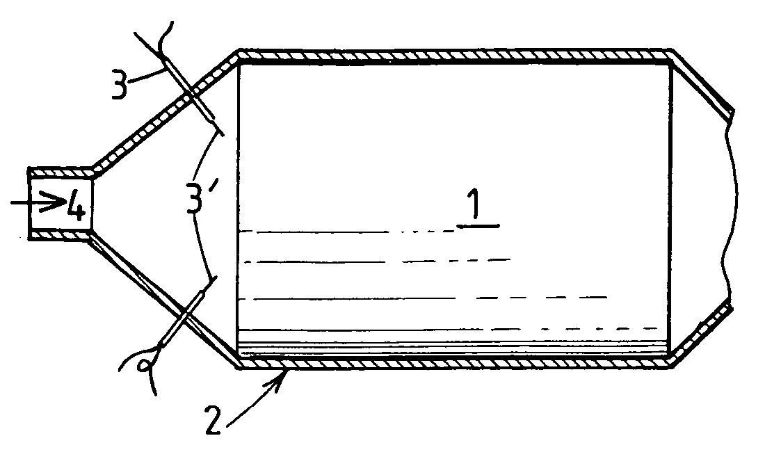
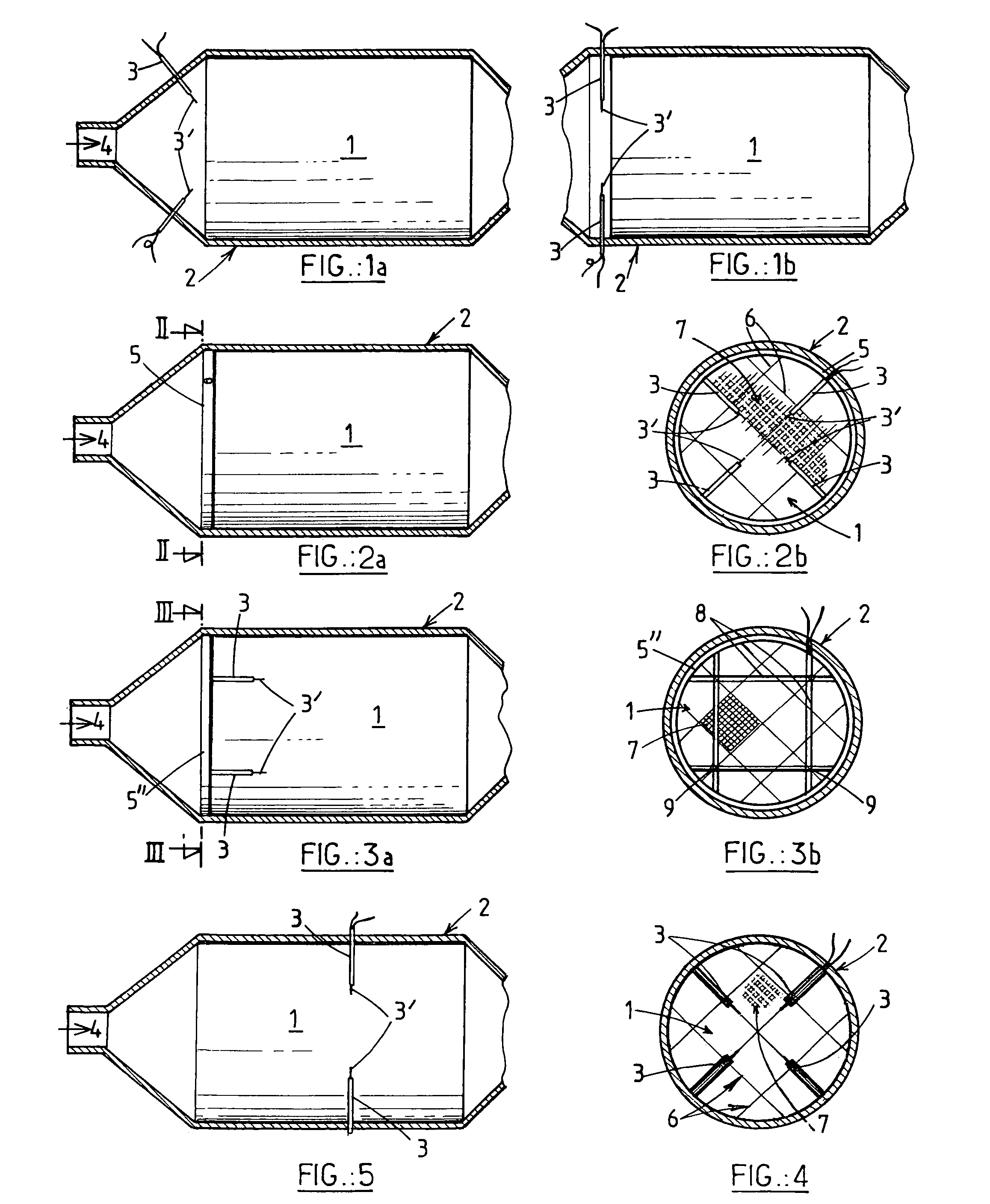
[0034]FIGS. 1a and 1b show a filter comprising a filter body 1 accommodated in a metal casing 2. The filter body 1 is constructed of blocks bonded together and pierced by many passages, as shown more clearly in FIG. 2b. Exhaust gases arrive via an inlet 4. In the two embodiments shown, four hot spot ceramic ignitors 3 (of which only two can be seen in FIGS. 1a and 1b) pass through the metal casing 2. They are positioned in pairs in orthogonal planes and either obliquely to the longitudinal axis of the filter (FIG. 1a) or perpendicularly to that axis (FIG. 1b), so that the hot spot 3′ of each ignitor is in the immediate vicinity of the upstream face of the filter body. Thus the heat emitted and the radiation ignite the soot and initiate its combustion by propagating into all of the filter body.

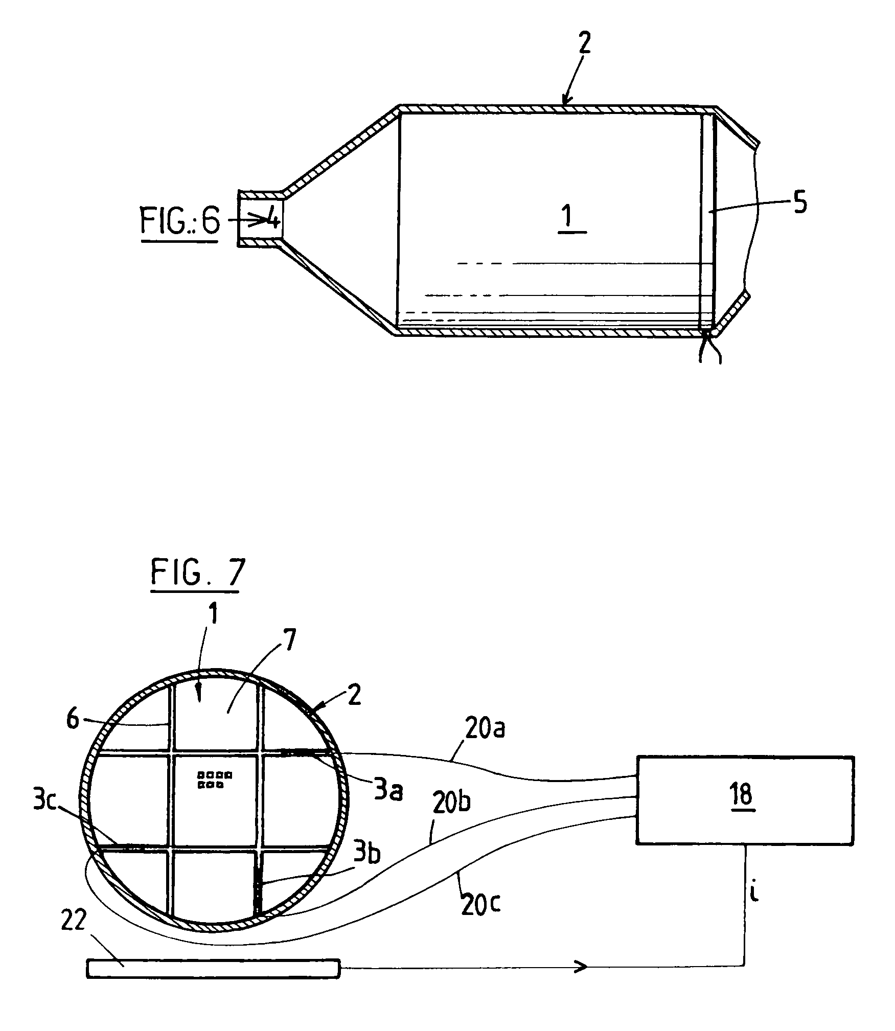
[0035]FIGS. 2a and 2b show an embodiment in which ignitors are carried by a ring 5 disposed in the metal casing 2 immediately in front of the filter body 1. To position the ring very accurately...


PUM

PropertyMeasurementUnit
self-ignition temperatureaaaaaaaaaa
temperatureaaaaaaaaaa
self-ignition temperatureaaaaaaaaaa

Abstract

A particulate filter for purifying exhaust gases of an internal combustion engine, in particular of a diesel engine, comprises a filtering body and heating elements for initiating combustion of soot particles accumulated on and in the filtering body. The heating elements comprise at least a hot spot ceramic ignitor (3). The invention is applicable in the automotive industry.

Description

CROSS REFERENCE TO RELATED APPLICATIONS[0001]This is the 35 USC 371 National Stage of International Application PCT / FR01 / 03358 filed on 29 Oct. 2001, which designated the United States of America.FIELD OF THE INVENTION[0002]The invention relates to the use of ceramic ignitors to regenerate particulate filters for purifying exhaust gases of internal combustion engines, in particular diesel engines fitted to automobile vehicles.BACKGROUND OF THE INVENTION[0003]Honeycomb porous structures are used as filter bodies for filtering particles emitted by diesel vehicles. The filter bodies are usually made of ceramic (cordierite, silicon carbide, etc.). They can be monolithic or assembled from a plurality of blocks. In the latter case, the blocks are bonded together with a ceramic cement. The assembly is then machined to the required section, which is usually round or oval. The filter body can include a plurality of passages which are closed at one end or the other, can have different shapes ...

Claims


Application Information

Patent Timeline
Patent Type & Authority Patents(United States)
IPC IPC(8): B01D46/00F01N3/02B01D46/42F01N3/027
CPCF01N3/027Y10S55/10Y10S55/30
Inventor BARDON, SEBASTIENWILLKENS, CRAIG
Owner SAINT GOBAIN CENT DE RES & DEVS & DETUD EUROEN
Why Eureka
Try Eureka