Flat dynamic radiation detector

a dynamic radiation and detector technology, applied in the field of radiometers, can solve the problems of adverse effects on successive image exposure, slow decay behavior of the photosensor arrangement or the second converter layer, and detrimental decay behavior, etc., to enhance the stability of dark images, increase the sensitivity of the first converter layer, and ensure the effect of stability

Inactive Publication Date: 2006-01-24
KONINKLIJKE PHILIPS ELECTRONICS NV
View PDF26 Cites 13 Cited by
  • Summary
  • Abstract
  • Description
  • Claims
  • Application Information

AI Technical Summary

Benefits of technology

[0014]To this end, it is proposed to provide a supporting layer between the converter arrangement and the illumination device, which supporting layer on the one hand provides a homogeneous light distribution and on the other hand has adequate mechanical stability for stable accommodation and support of the converter arrangement provided on the supporting layer. The homogeneous light distribution is required for effective resetting of the converter arrangement and is realized by way of the layer of air in conformity with the state of the art. The homogeneous light distribution is achieved notably in that a layer of a synthetic material, for example, an acrylic layer, is provided between the converter arrangement and the illumination device. Such a layer has the necessary light absorption, thermal conductivity and also mechanical stability to support the converter arrangements provided over such a layer.
[0015]The illumination device emits the reset light notably in the direction of the overlying converter arrangement. In that case it is particularly effective to select a wavelength which lies in the sensitivity range of the converter arrangement. It is advantageous to choose light of a wavelength in the range of from 300 to 900 nm in such a case.
[0016]The supporting layer in a preferred embodiment of the invention is provided with cooling medium chambers which can receive a cooling liquid so that heat can be very effectively carried off in the radiation detector. A constant temperature in the

Problems solved by technology

It has been found that the photosensor arrangement or second converter layer exhibits a slow decay which has an adverse effect on successive image exposures.
Such a decay behavior is detrimental notably when many images are acquired per unit of time.
However, because so-called traps occur in the semiconductor layer of the photosensor arrangement due to contaminations and grid defects, many electrons remain behind in the semiconductor layer.
Normally speaking the charge carriers present in the traps are thermally emitted in the course of time and transferred to the electrodes, be it that this may take a long period of time.
Direct arrangement of the illu

Method used


Image

  • Flat dynamic radiation detector
  • Flat dynamic radiation detector

Examples


Embodiment Construction

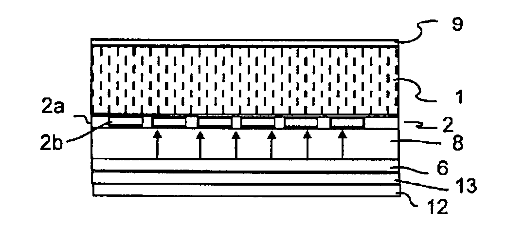
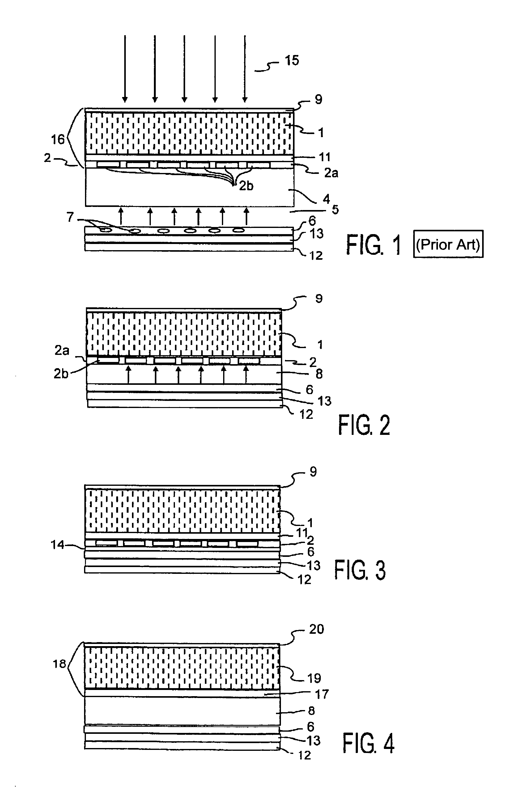
[0036]FIG. 1 shows the construction of a radiation detector in conformity with the state of the art. The converter arrangement 16 thereof is formed essentially by a first converter layer 1 and a second converter layer 2. The converter layer 1 is connected, via an adhesive layer 11, to the glass plate 2a with the photosensor arrangement 2b provided thereon in the thin-film technique, for example, by amorphous silicon technology 11. Above the converter layer 1 there is provided a reflection layer 9 which reflects upwards reflected light back in the direction of the photosensor arrangement. The glass support 4 carries the glass plate 2a with the photosensor arrangement 2b provided thereon and the converter layer 1 arranged thereabove. Underneath the glass support 4 there is formed a layer of air 5 of a thickness of approximately 10 mm. The illumination device 6 with light-emitting diodes (LEDs) 7 is provided underneath said layer of air 5. The incident X-rays 15 pass the reflection lay...


PUM


Abstract

The invention relates to a radiation detector for converting electromagnetic radiation (15) into electric charge carriers. The invention also relates to an X-ray examination apparatus provided with such a radiation detector, and to a method of manufacturing a radiation detector. In order to achieve a small building height of the radiation detector while nevertheless satisfying the same requirements as regards the resetting of the converter arrangement (16, 18) by means of an illumination device (6), it is proposed to provide a supporting layer (8) underneath a glass plate (2a) with a photosensor arrangement (2b), which supporting layer on the one hand provides uniform distribution of the light incident from below and on the other hand imparts the necessary stability to the radiation detector. In a further embodiment it is proposed to provide a scatter foil (14) instead of the supporting layer (8), which scatter foil provided the homogeneous light distribution while the supporting function is taken over by the illumination device.

Description

BACKGROUND[0001]The invention relates to a radiation detector for converting electromagnetic radiation into electric charge carriers. The invention also relates to an X-ray examination apparatus provided with radiation detector of this kind and to a method of manufacturing a radiation detector.[0002]Radiation detectors are used notably in the medical field, that is, for X-ray examinations, and serve to form radiation images of an object to be examined, usually a patient, in the context of mostly a medical examination or therapy. An image pick-up system which also includes the X-ray detector is used to form images of the object to be examined which is exposed to the X-rays, said images being output, for example, via a monitor. The X-rays incident on the X-ray detector are converted into electric charge carriers in a converter arrangement. The electric charge carriers generated in the converter arrangement are collected in associated capacitances so as to be read out by a downstream e...

Claims


Application Information

Patent Timeline
IPC IPC(8): G01T1/24G01T1/20H01J47/02H01L31/09H04N5/32
CPCG01T1/2018G01T1/2002
Inventor WISCHMANN, HANS-ALOYSWIECZOREK, HERFRIED KARLBUSSE, FALKOSCHMIDT, RALF
Owner KONINKLIJKE PHILIPS ELECTRONICS NV
Why Eureka
Try Eureka