Electric current detector with hall effect sensor

a technology of electric current detector and hall effect sensor, which is applied in the direction of magnetic measurement, instruments, measurement devices, etc., can solve the problems of reducing productivity and yield, affecting the effect of automation, so as to facilitate the attachment of the detector and restrict or reduce the deterioration of electric properties

Inactive Publication Date: 2006-01-24
SANKEN ELECTRIC CO LTD
View PDF4 Cites 65 Cited by
  • Summary
  • Abstract
  • Description
  • Claims
  • Application Information

AI Technical Summary

Benefits of technology

[0008]The electric current detector according to the present invention comprises a Hall effect sensor (2), a plurality of lead terminals (3) electrically connected to the Hall effect sensor (2), a plastic package (4) for encapsulating the Hall effect sensor (2) and each inner end of the lead terminals (3), and a conductor (6) loosely disposed with a gap in an opening (5) formed in the plastic package (4) and in spaced relation to the Hall effect sensor (2) to pass a detected electric current through the conductor (6). The loose arrangement of the conductor (6) provides the air gap or air layer between the conductor (6) and plastic package (4) in the opening (5) to prevent close contact between the conductor (6) and plastic package (4). Accordingly, heat and heat stress that m...

Problems solved by technology

In this current detector, however, a problem arises that it requires troublesome and complicated assembling processes for inserting the conductor such as a wire into the through hole in the plastic package at a predetermined height, and thereby the assembling process impedes the changeover to automation of assembling process for the detectors.
However, a large electric current flowing through the conductor heats the conductor to thereby cause heat...

Method used


Image

  • Electric current detector with hall effect sensor
  • Electric current detector with hall effect sensor
  • Electric current detector with hall effect sensor

Examples


example

[0056]To confirm the effects obtained from the present invention, the electric current detector 1 was prepared and tested in the following procedure:

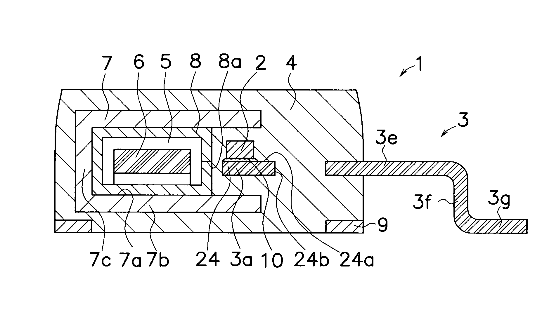
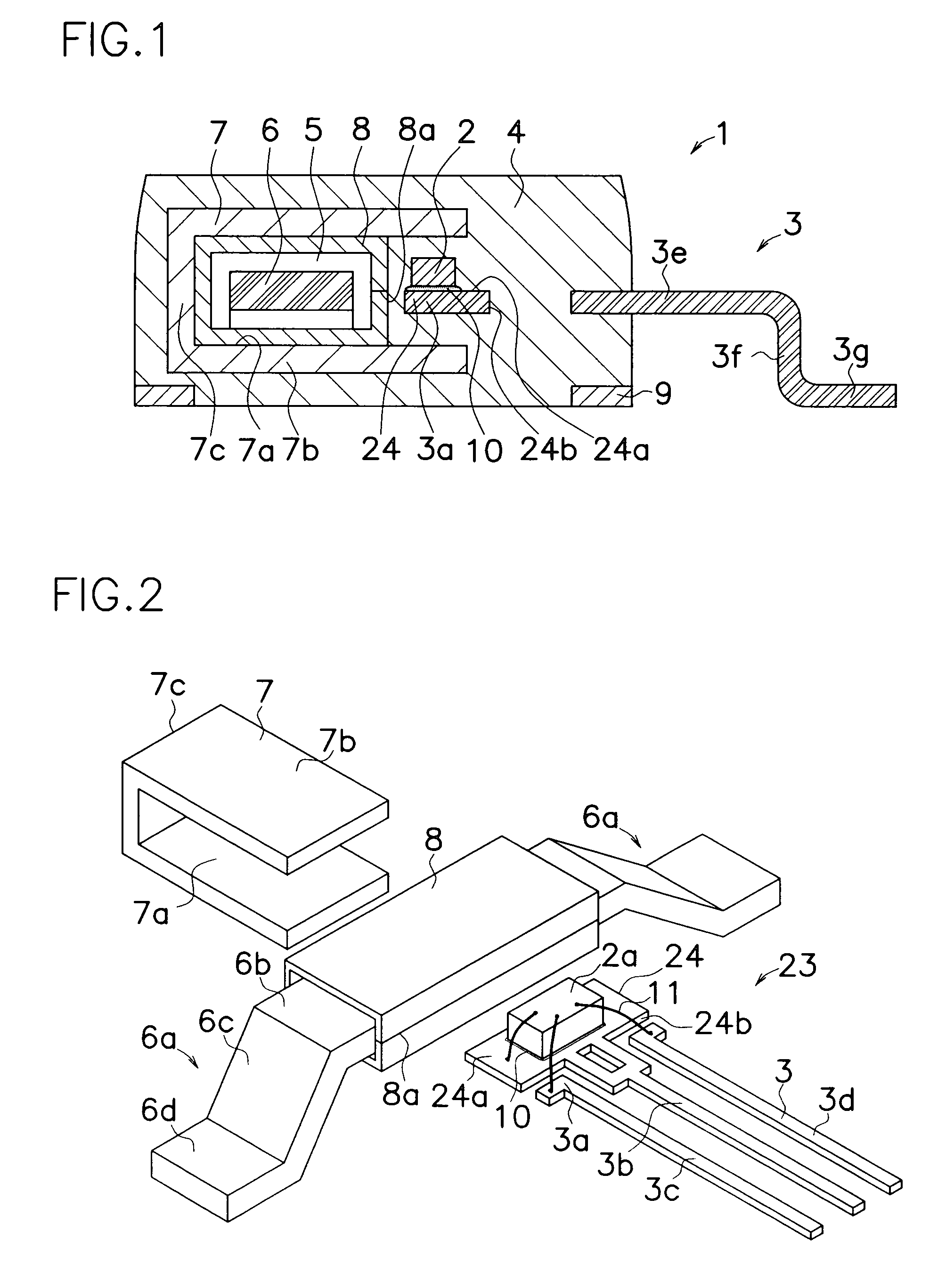
[0057]The electric current detector 1 was prepared that comprises Hall effect sensor 2, leadframe assembly 23 having three lead terminals 3, ferrite core 7, reinforcement tube 8, metallic pads 9 and package 4 formed with opening 5 for encapsulating these elements. Reinforcement tube 8 was made of phosphor bronze with the length of 2.7 millimeters. Conductor 6 was made of copper plate with nickeled surfaces with the top beam 6a of 0.8 millimeter in thickness.

[0058]When the resultant electric current detector 1 was mounted on a surface of substrate, top beam of conductor 6 could be mounted in position on the surface of substrate on the same level of conductor 6 as lead terminals 3 after conductor 6 was vertically and longitudinally moved in opening 5. In other words, an air-gap was formed between outer surfaces of conductor 6 and inner su...


PUM


Abstract

An electric current detector is provided wherein loose arrangement of conductor 6 in opening 5 provides an air gap between the conductor 6 and plastic package 4 in opening 5 to prevent close contact of conductor 6 to plastic package 4. When heat and heat stress are produced in conductor 6 by a large electric current flowing through conductor 6 during measurement, air gap surely prevents heat and heat stress from traveling to Hall effect sensor 2 and plastic package 4 while a part of heat in conductor 6 is radiated into air in opening 5. Thus, the loose arrangement of conductor 6 can restrict or reduce deterioration of electric property in Hall sensor 2 and degradation of mechanical property in plastic package 4 by heat and heat stress in conductor 6. Also, the loose arrangement ensures and facilitates attachment of the detector 1 in position on a surface of a substrate, and enables to maintain conductor 6 at the same level as lead terminals 3 of the detector.

Description

TECHNICAL FIELD[0001]The present invention relates to an electric current detector, in particular of the type provided with a Hall effect sensor for detecting an electric current flowing through a conductor in the detector while preventing deterioration of the Hall effect sensor.BACKGROUND OF THE INVENTION[0002]A device for detecting an electric current with a Hall effect sensor is known for example by Japanese Patent Disclosure No. 1-145837. The detecting device comprises a support pad, a plurality of lead terminals mounded around the support pad, a Hall effect sensor attached on a main surface of the support pad, wires for electrically connecting electrodes and lead terminals, and a plastic package for sealing the Hall effect sensor, wires, support pad and each inner end of the lead terminals. Flow of electric current through an object produces a magnetic field normal to the flowing direction of the electric current in the object, and placement of the detecting device in the magne...

Claims


Application Information

Patent Timeline
IPC IPC(8): G01R33/07H01L43/04G01R15/20G01R19/00
CPCG01R19/0092G01R15/202
Inventor GOTO, HIROKAZU
Owner SANKEN ELECTRIC CO LTD
Why Eureka
Try Eureka