
Correlator

Inactive Publication Date: 2006-01-24
NEC CORP
View PDF12 Cites 13 Cited by
  • Summary
  • Abstract
  • Description
  • Claims
  • Application Information

AI Technical Summary

Benefits of technology

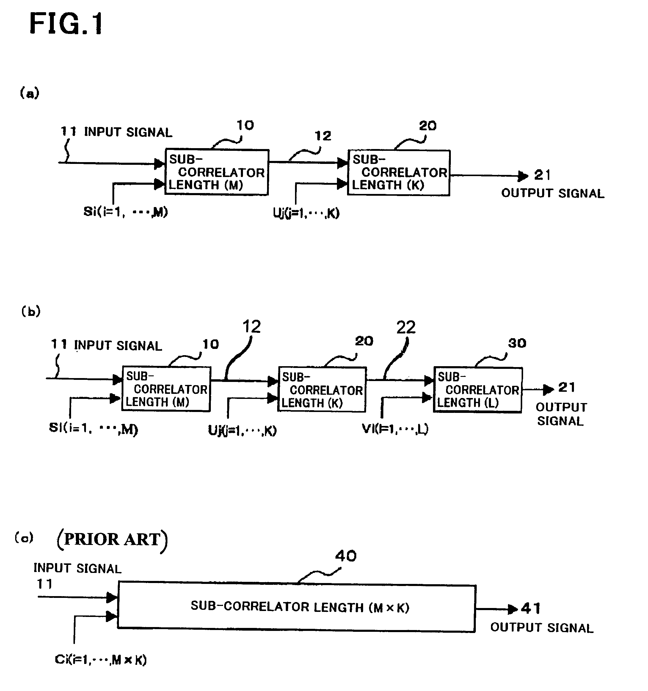
[0055]As mentioned above, the correlator in accordance with the present invention is designed to include a sub-correlator having a length of M chip and a sub-correlator having a length of K symbol. This structure provides advantages that a circuit size can be reduced, and the correlator can calculate a correlation value equivalently to a correlator having a length N chip (N=M×K).
[0056]Furthermore, the present invention provides an advantage that the second sub-correlators by the number equal to the number of kinds of fixed patterns can calculate correlation values for a plurality of fixed patterns with an increase in a circuit size being prevented.

Problems solved by technology

As a result, the correlator would consume much power, resulting in increasing difficulty in saving power consumption and fabrication in lower cost in a mobile terminal device such as a CDMA cellular phone.
In addition, if the correlator illustrated in FIG. 8 were designed to be longer, the shift register 301 would have to be constructed longer, resulting in that calculation of a correlation value would take longer time, and hence, it would take longer time until synchronization capture is accomplished.
Accordingly, a time necessary for obtaining a correlation value increases in proportion to the length N, and hence, it would take much time to accomplish synchronization capture.
However, the conventional correlators illustrated in FIGS. 7 and 8 cannot meet such requirements as mentioned above.

Method used


Image

  • Correlator
  • Correlator
  • Correlator

Examples


first embodiment

[0069]FIG. 1(c) illustrates a conventional correlator 40 used for detecting correlation for a certain length N (N=M×K) similarly to the correlator in accordance with the

[0070]In the correlator in accordance with the first embodiment, a total length of the first and second sub-correlators 10 and 20 is equal to (M+K). Hence, the correlator in accordance with the first embodiment can significantly reduce a circuit size in comparison with the conventional correlator having a length of (M×K), illustrated in FIG. 1(c).

[0071]In addition, since a total length of the first and second sub-correlators 10 and 20 is equal to (M+K), it would be possible to increase an operation rate in the correlator.

[0072]For instance, if the correlator illustrated in FIG. 8 were comprised of the first sub-correlator 10 and the second sub-correlator 20 both illustrated in FIG. 1(a), a time necessary for calculation of a correlation value is in proportion to not (M×K), but (M+K).

[0073]The correlator in accordance...

second embodiment

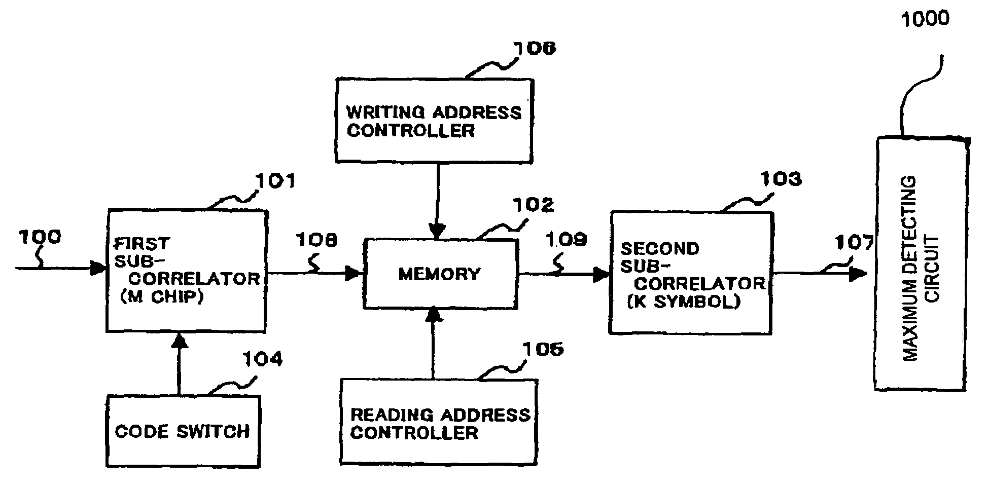
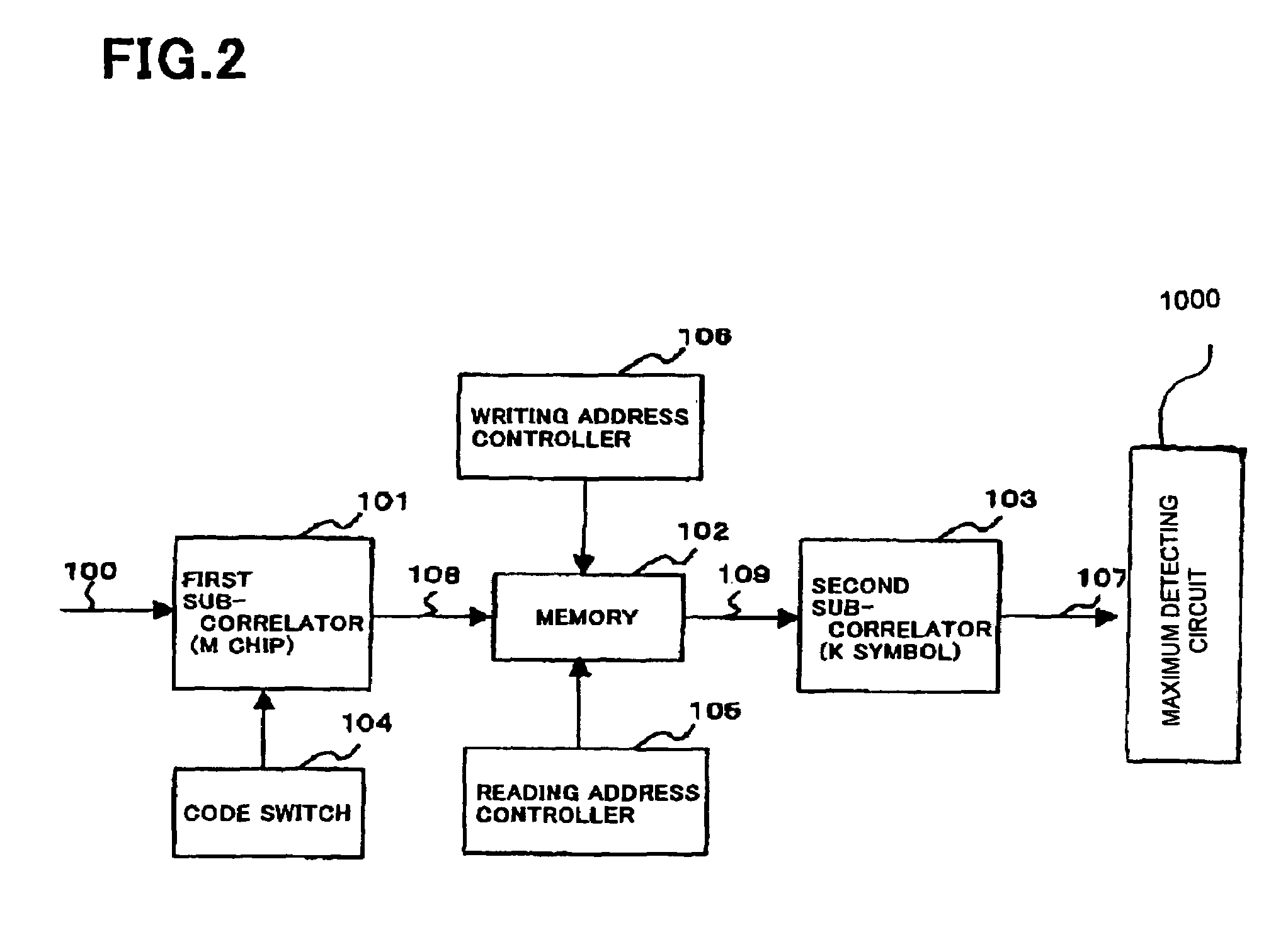
[0150]The correlator in accordance with the second embodiment is comprised of a first sub-correlator 101, a code switch 104 which switches pseudorandom noise code rows to be supplied to the first sub-correlator 101, a memory 102, a reading address controller 105 which controls an address for reading data out of the memory 102, a writing address controller 106 which controls an address for writing data into the memory 102, and X second sub-correlators 1031 to 103X connected in parallel with one another to the memory 102.

[0151]The correlator in accordance with the second embodiment is structurally different from the correlator in accordance with the first embodiment, illustrated in FIG. 2, in including a plurality of second sub-correlators 1031 to 103X connected in parallel with the memory 102.

[0152]The number X of the second sub-correlators 1031 to 103X is equal to the number of kinds of fixed symbols constituting a fixed pattern.

[0153]That is, the correlator in accordance with the p...

third embodiment

[0166]Hereinbelow is explained the correlator in accordance with the

[0167]The correlator in accordance with the third embodiment basically has the same structure as that of the correlator in accordance with the first embodiment, illustrated in FIG. 2, but is structurally different from the first embodiment in terms of the second sub-correlator.

[0168]FIG. 6 is a partial block diagram of the correlator in accordance with the third embodiment.

[0169]If it is not necessary in the first embodiment illustrated in FIG. 2 to use a correlation value transmitted from the second sub-correlator 103, and it is only necessary to judge whether the correlation value and a fixed word are identical with each other, a comparator 110 which compares the correlation value 108 transmitted from the first sub-correlator 101, to a fixed word may be used in place of the second sub-correlator 103, as illustrated in FIG. 6.

[0170]Specifically, if it is not always necessary to have all correlation values, and it i...


PUM


Abstract

A correlator which detects correlation for data having a certain length includes a plurality of sub-correlators, each of the sub-correlators having a length equal to a divisor of the certain length and each of the sub-correlators having such a length that a product of all lengths of the sub-correlators is equal to the certain length. A correlation value output from one of the sub-correlators is input into a sub-correlator located immediately downstream of one of the sub-correlators.

Description

BACKGROUND OF THE INVENTION[0001]1. Field of the Invention[0002]The invention relates to a correlator, and more particularly to a correlator suitable to a CDMA type receiver.[0003]2. Description of the Related Art[0004]As is known, in spread spectrum system, a signal is modulated by a transmitter, spectrum-spread through the use of pseudorandom noise code, and then, transmitted. A receiver inverse-spreads a received signal through the use of pseudorandom noise code which is identical with the pseudorandom noise code (PN) having been used by a transmitter for spread, in order to demodulate the received spectrum-spread signal.[0005]In these days, CDMA (Code Division Multiple Access) communication system in which spread-spectrum type pseudorandom noise code is assigned to each communication is expected as a standard radio-communication system for a mobile terminal in a mobile communication system.[0006]In the CDMA communication system, for instance, user data spread with pseudorandom n...

Claims


Application Information

Patent Timeline
IPC IPC(8): H04B1/707G06F17/15H04B1/709
CPCG06F17/15H04B1/707H04B1/709H04B1/7093H04B1/7077H04B2201/70707
Inventor IWASAKI, MOTOYA
Owner NEC CORP
Learn More