Evaluation circuit for a current sensor using the compensation principle, in particular for measuring direct and alternating currents, and a method for operating such a current sensor

a current sensor and compensation principle technology, applied in the field of current sensors, can solve the problems of difficult direct implementation of peak-type rectification of probe signals in integrated circuits, and achieve the effect of improving resolution and smoothing compensation currents

Inactive Publication Date: 2006-01-24
SIEMENS AG
View PDF23 Cites 17 Cited by
  • Summary
  • Abstract
  • Description
  • Claims
  • Application Information

AI Technical Summary

Benefits of technology

[0018]According to yet another advantageous feature of the invention, the characteristic times of the digital signals are measured by forming the difference between the times of the positive and the negative modulation amplitude of the magnetic field probe, with the time difference being controlled to zero so as to eliminate deviations from zero magnetic flux.
[0021]Advantageously, the winding of the magnetic field probe can be briefly short-circuited during excitation, in particular for one clock cycle during every second or multiple measurement, in order to improve resolution.
[0022]According to another advantageous feature, the compensation current can be smoothed by using the inductance of the compensation winding.

Problems solved by technology

However, it has proven difficult to directly implement a conventional peak-type rectification of the probe signal in an integrated circuit.

Method used


Image

  • Evaluation circuit for a current sensor using the compensation principle, in particular for measuring direct and alternating currents, and a method for operating such a current sensor
  • Evaluation circuit for a current sensor using the compensation principle, in particular for measuring direct and alternating currents, and a method for operating such a current sensor
  • Evaluation circuit for a current sensor using the compensation principle, in particular for measuring direct and alternating currents, and a method for operating such a current sensor

Examples


Embodiment Construction

[0032]Throughout all the Figures, same or corresponding elements are generally indicated by same reference numerals. These depicted embodiments are to be understood as illustrative of the invention and not as limiting in any way.

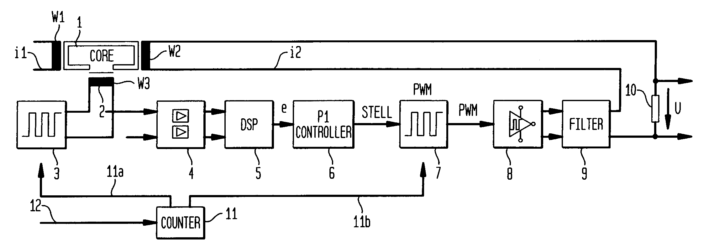
[0033]Turning now to the drawing, and in particular to FIG. 1, there is shown a schematic diagram of a compensation current transformer, operating according to the evaluation method and having an evaluation circuit according to the invention. Shown on the left of FIG. 1 is the magnetic part, which includes a main core 1 with primary winding w1 and compensation winding w2, as well as a magnetic flux or magnetic field probe 2. The primary winding w1 conducts the measuring current i1 and has a substantially lower number of turns per unit length (possibly only one turn) than the compensation winding w2. The flux probe 2 consists, for example, of a Vitrovac® strip and a sensor coil w3.

[0034]The drive 3, an oscillator, excites the magnetic field probe 2. This is f...


PUM


Abstract

A current sensor using the compensation principle, in particular for measuring direct and alternating currents, includes an entirely digital evaluation circuit for signal processing. This substantially lowers the cost of the control electronics, in particular through integration in an ASIC. The magnetic field probe is, for example, supplied with a square wave voltage of a predetermined frequency, the probe signal is recorded by one or two comparators and the pulse width is digitally measured by counters. Furthermore, the conventional analog final stage for the compensation current is replaced by a PWM end stage with a series connected sigma-delta modulator. The square wave can be synchronized with a defined synchronization signal, which can be derived, for example, from the processed measurement values.

Description

CROSS-REFERENCES TO RELATED APPLICATIONS[0001]This application is a continuation of prior filed copending PCT International application no. PCT / DE01 / 03356, filed Sep. 3, 2001, which designated the United States and on which priority is claimed under 35 U.S.C. §120, the disclosure of which is hereby incorporated by reference.[0002]This application claims the priority of German Patent Application, Serial No. 100 45 194.2, filed Sep. 13, 2000, pursuant to 35 U.S.C. 119(a)–(d), the disclosure of which is incorporated herein by reference.BACKGROUND OF THE INVENTION[0003]The present invention relates to a current sensor for measuring direct and alternating currents, and more particularly to a current sensor operating by compensating a magnetic field introduced by the current.[0004]Current sensors of this type are known in the art as compensation current transformers and measure direct and alternating currents by compensating the magnetic field generated in a magnet core by the measuring c...

Claims


Application Information

Patent Timeline
Patent Type & Authority Patents(United States)
IPC IPC(8): G01R15/00G01R15/18
CPCG01R15/185
Inventor K PKEN, HANS-GEORG
Owner SIEMENS AG
Why Eureka
Try Eureka