
Rotatable air knife

a technology of rotating blades and air knives, which is applied in the direction of drying machines with progressive movements, lighting and heating apparatus, furniture, etc., can solve the problems of mechanical drive mechanism, achieve the effect of reducing the number of rotations

Inactive Publication Date: 2006-01-31
SONIC AIR SYST
View PDF18 Cites 42 Cited by
  • Summary
  • Abstract
  • Description
  • Claims
  • Application Information

AI Technical Summary

Benefits of technology

"The present invention is an improved air knife or air distribution manifold for cleaning or blowing off articles. The air knife or manifold is designed to rotate about a central axis, which allows it to be positioned in different directions relative to the conveyor system. This increases the time the article is exposed to the air, resulting in more effective cleaning or drying. The air knife or manifold is constructed with laterally separated, opposing ends, and thrust nozzles that direct air in a tangential direction. The system does not require a mechanical drive mechanism to rotate the air knife or manifold. The air distribution enclosure is an elongated air knife that expels air in a band that extends linearly between its ends. The air knife or manifold can be used with a variety of different couplings to connect it to the blower duct. The invention is not limited to air knives with a single, long, narrow slot, and a manifold with separate primary nozzles can also be used instead of an air knife."

Problems solved by technology

Furthermore, the system requires no mechanical drive mechanism to rotate the air knife or air jet manifold.

Method used


Image

  • Rotatable air knife
  • Rotatable air knife
  • Rotatable air knife

Examples


Embodiment Construction

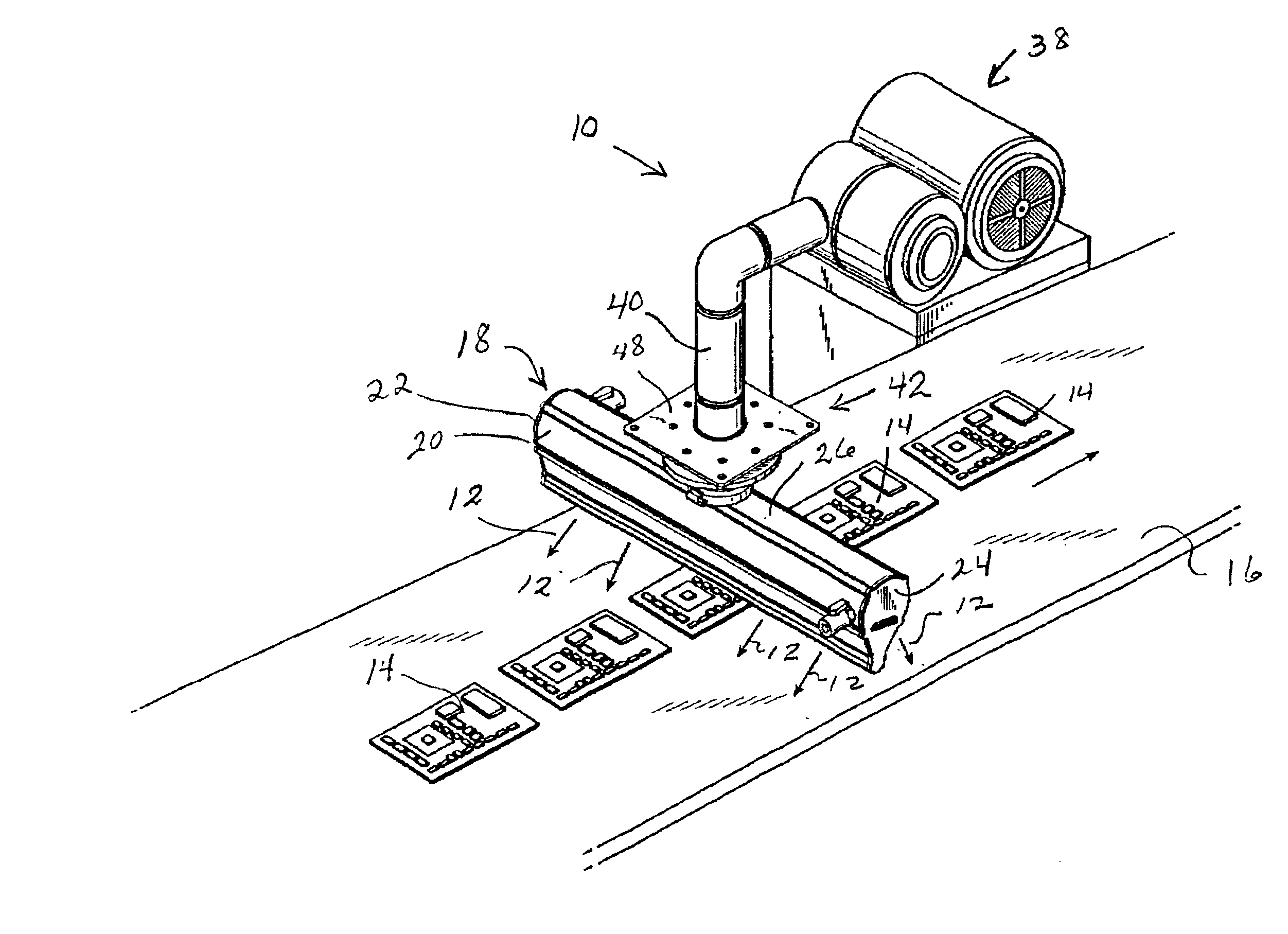
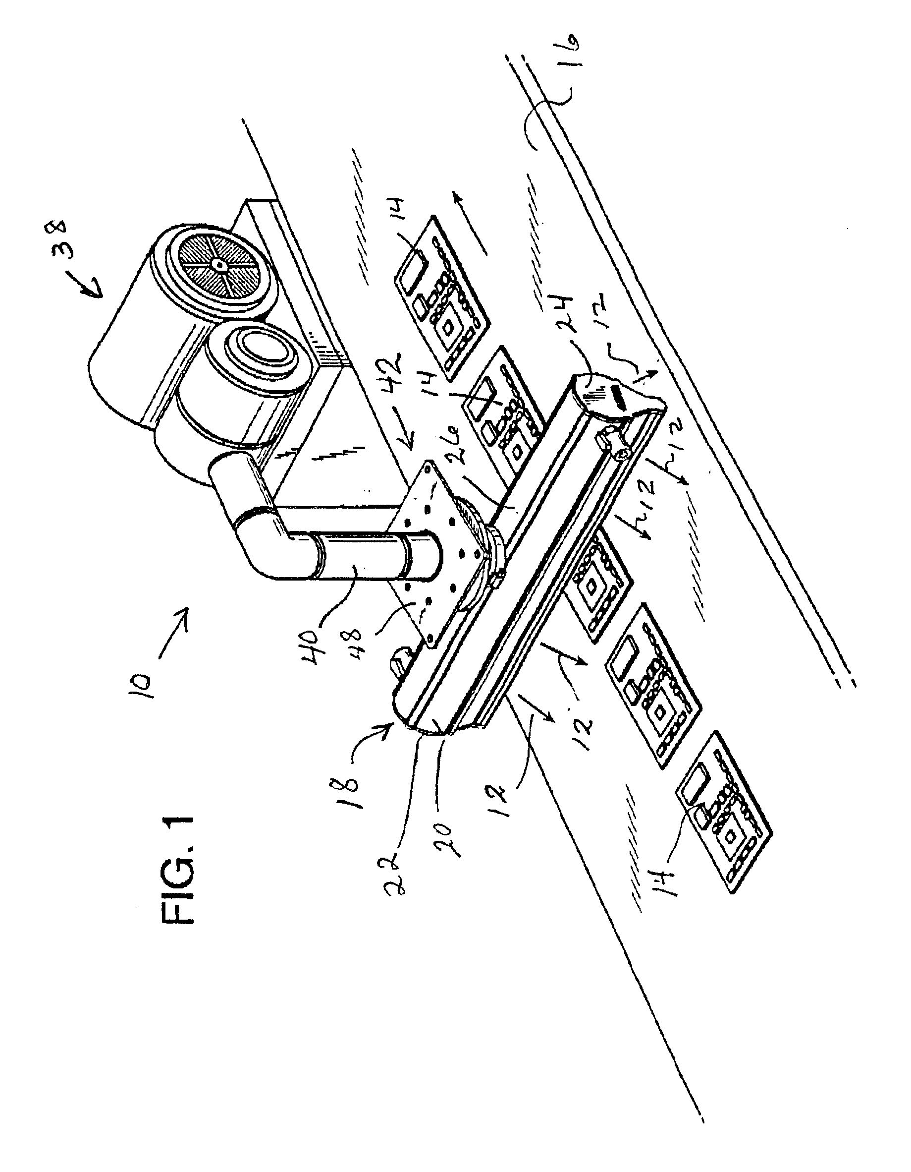
[0034]FIG. 1 illustrates an air knife assembly indicated generally at 10 which is used for directing a flow of air, indicated by the directional arrows 12 at passing articles 14. In the illustration shown, the articles 14 are printed circuit boards which are carried on a conveyor belt 16 beneath the air knife 18.

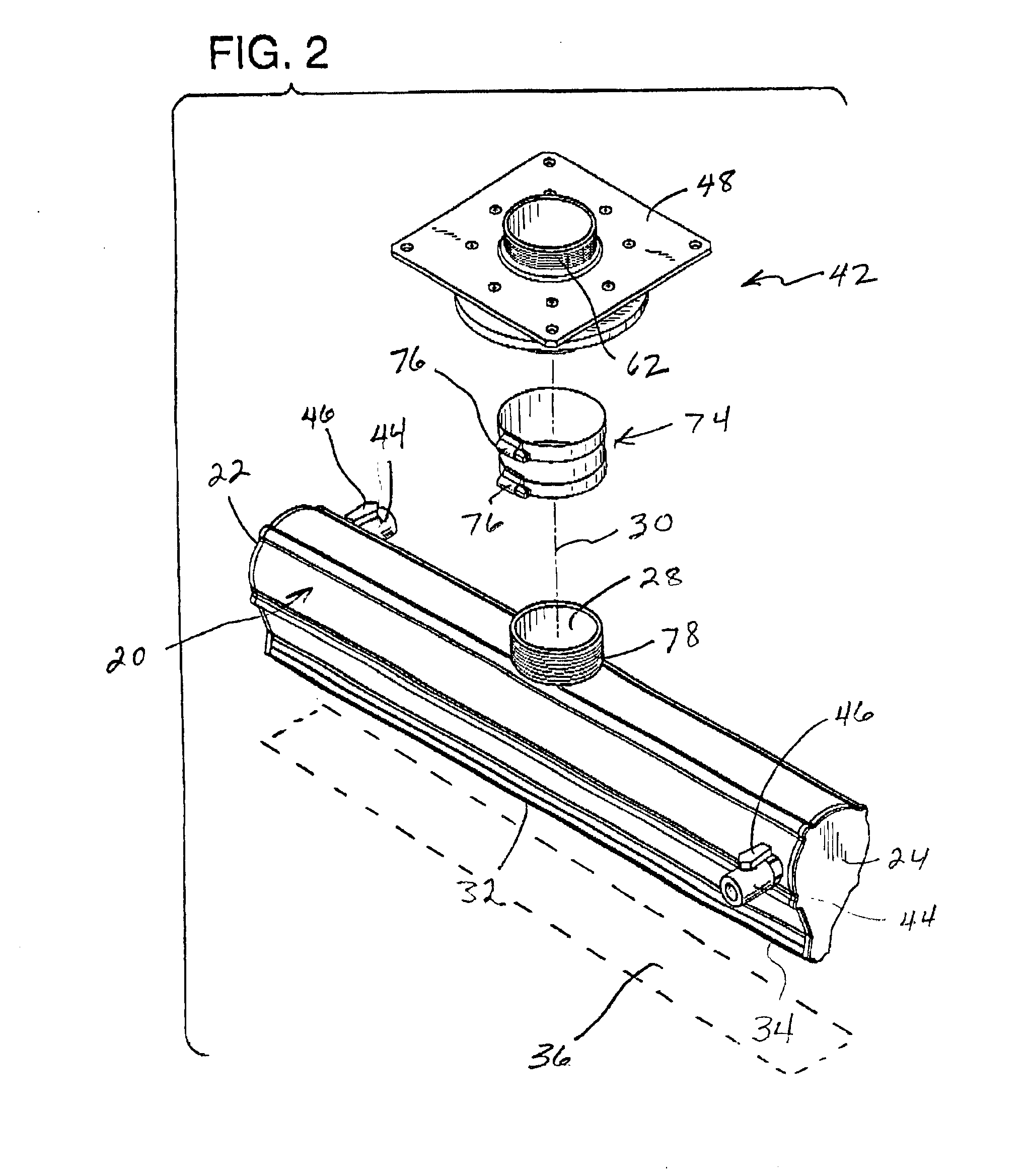
[0035]The air knife 18 is comprised of a hollow, elongated air distribution enclosure 20. The enclosure 20 is a tubular structure having opposing closed ends 22 and 24 with an inlet side 26 having a longitudinally aligned inlet opening 28 therein. The longitudinally aligned opening 28 is equidistant from the opposing ends 22 and 24 and is a circular opening centered upon a longitudinal axis 30. The air distribution enclosure 20 also has an outlet side 32 having a narrow, elongated slot 34 defined therein. The air distribution enclosure 20 emits a flow of air through the outlet slot 34 along an elongated linear band indicated in phantom at 36 in FIG. 2.

[0036]The air knife ass...


PUM


Abstract

An air knife or air nozzle manifold for drying or blowing off passing articles moved by a conveyor system is provided with a coupling that permits rotation of the air knife or air nozzle manifold relative to the air inlet duct leading from a blower. The air knife or air nozzle manifold has opposing ends located equidistant from a longitudinal axis of rotation relative to a stationary element of the coupling. Thrust nozzles are provided at each of the opposing ends of the air knife or air nozzle manifold to deflect a certain portion of the air from the plenum chamber to provide thrusting jets of air that rotate the air knife or air nozzle manifold about the longitudinal axis. The flow of air emitted from the air knife or air nozzle manifold is thereby directed onto the passing articles from different directions as the articles move by. The efficiency of drying and blowing off the articles to be processed is thereby significantly improved.

Description

BACKGROUND OF THE INVENTION[0001]1. Field of the Invention[0002]The present intervention is an apparatus, such as an air knife or an air distribution manifold, for directing air under pressure at passing articles to dry or remove dust and debris from those articles.[0003]2. Description of the Prior Art[0004]Conventional air knives and air distribution manifolds are often formed as elongated structures that extend alongside or transverse to a conveyor belt or conveyor chain carrying articles to be dried or blown clean. Air knives are extensively used for drying a wide variety of articles of manufacture, such as plastic soft drink bottles prior to labeling, printed electronic circuit boards, food packaging, and many other products. Conventional pressure air delivery devices in the form of air knives and air nozzles have been used in a wide variety of industrial and commercial processes to remove or control the amount of liquids remaining on the surfaces of products after washing, rins...

Claims


Application Information

Patent Timeline
Patent Type & Authority Patents(United States)
IPC IPC(8): F26B3/32F26B21/00
CPCF26B21/004
Inventor RILEY, TERENCE M.VANDERPYL, DANIEL J.
Owner SONIC AIR SYST
Learn More