High-energy combined well perforating device

a perforating device and high-energy technology, applied in the direction of wellbore/well accessories, nuclear explosives, nuclear engineering, etc., can solve the problems of increasing the potential failure of safety, reducing the efficiency of assembly, so as to reduce the efficiency of assembly and facilitate assembly. , the effect of simple techniqu

Inactive Publication Date: 2006-01-31
XIAN TONGYUAN PETROTECH
View PDF14 Cites 24 Cited by
  • Summary
  • Abstract
  • Description
  • Claims
  • Application Information

AI Technical Summary

Benefits of technology

[0030]In comparison with the Chinese utility model patent No. 97242235.8, the present invention changes the powder sleeve or the solid-propellant sleeve into a unit perforator constructed from an explosive box in which energetic material is contained. The unit perforator can be manufactured with a simple technique and is suitable for a commercial production and is convenient to be assembled when utilized, thus the difficulty in manufacturing the powder sleeve or the solid-propellant sleeve is solved and the problem of having to cut the solid-propellant that will decrease the efficiency of assemble and increase the potential failure in safety can be avoided. Therefore the present invention is featured by its simple process and is suitable for a commercial production.
[0031]The present invention changes the circular steel plate for covering the pressure-relief vent into an arched steel plate or a chamfered circular steel plate. The arched steel plate or the chamfered circular steel plate is attached with a rubber sealing material which may improve the resistance to deformation and insure good sealing for the down hole perforating gun.
[003...

Problems solved by technology

The structure of the powder sleeve or the solid-propellant sleeve is difficult to realize through a certain manufacturing process, moreover before the down hole operation in the oil field it is required to cut the composite solid-propellant sleeve, which decreases the efficiency of assembling and increases the potential failure in safety.
Since the rubber layer of said sealing cap is only combined with the upper surface of the circular steel plate, under the action of pressure, temperature and chemical medium, said rubber layer is fallen off easily and loses its sealing function, then water may flow into the perforating gun, which may extinguish the detonating cord even a failure of gun explosion will happen.
Moreover, in the above-mentioned patent, the positioning mechanism between the charge strip and the perforating gun can only position the charge strip in the perforating gun radically and can not position the charge strip in the perforating gun axially which is not only detrimental to detonation propa...

Method used


Image

  • High-energy combined well perforating device
  • High-energy combined well perforating device
  • High-energy combined well perforating device

Examples


Embodiment Construction

[0051]The invention will be described in detail in connection with the embodiments by referring to the accompanying drawings.

[0052]FIGS. 1˜9 show schematically the structure of the first embodiment according to the invention.

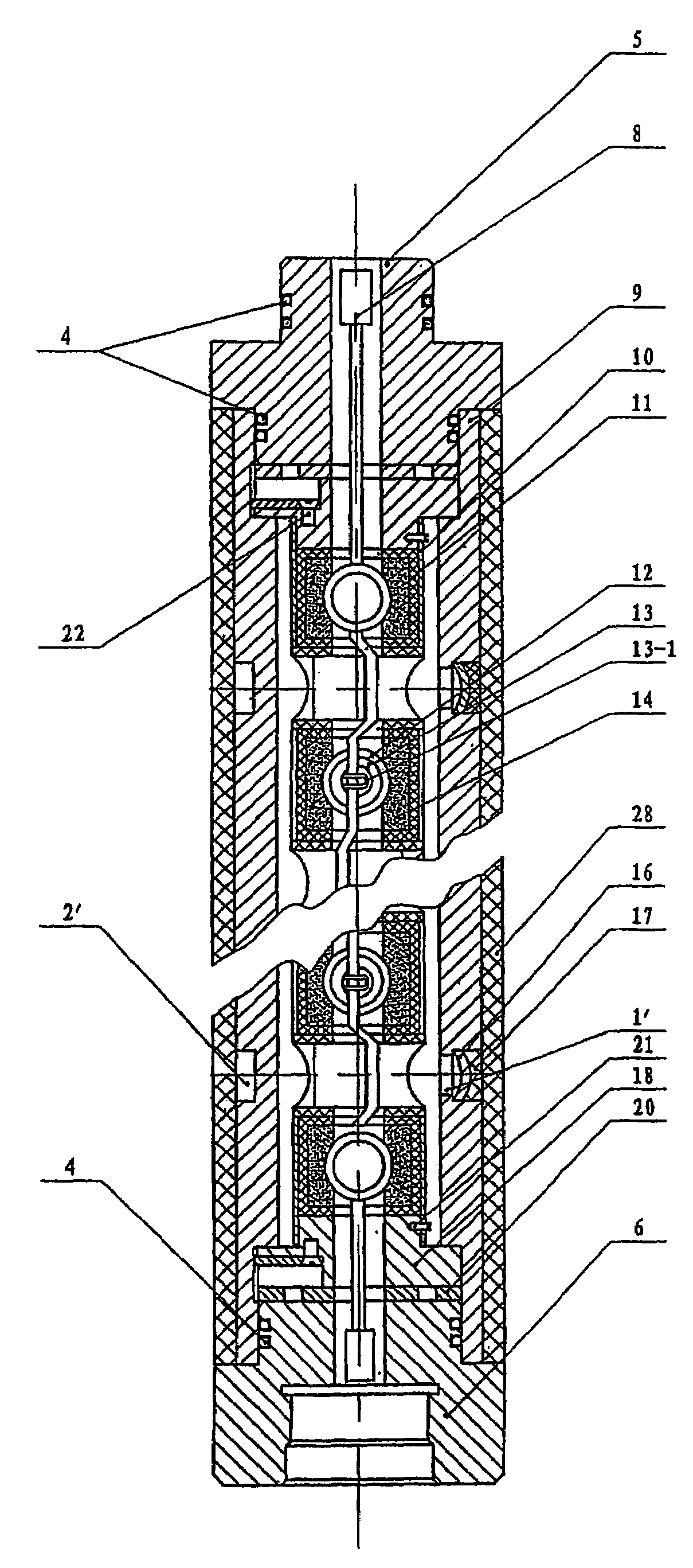
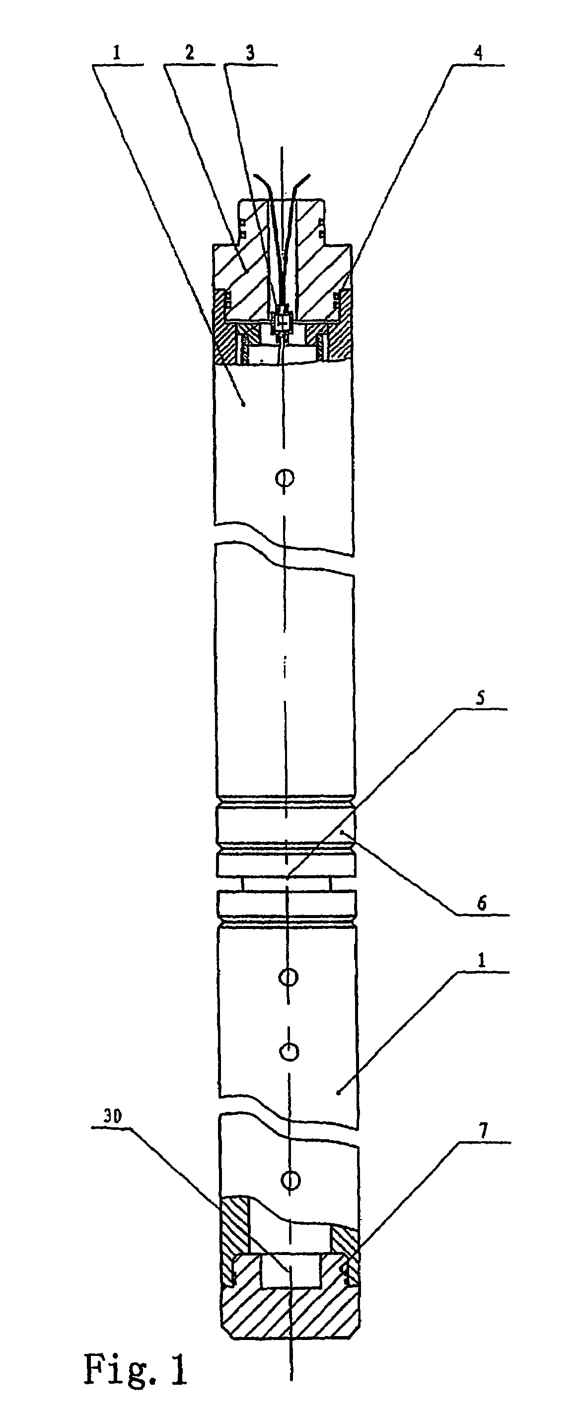
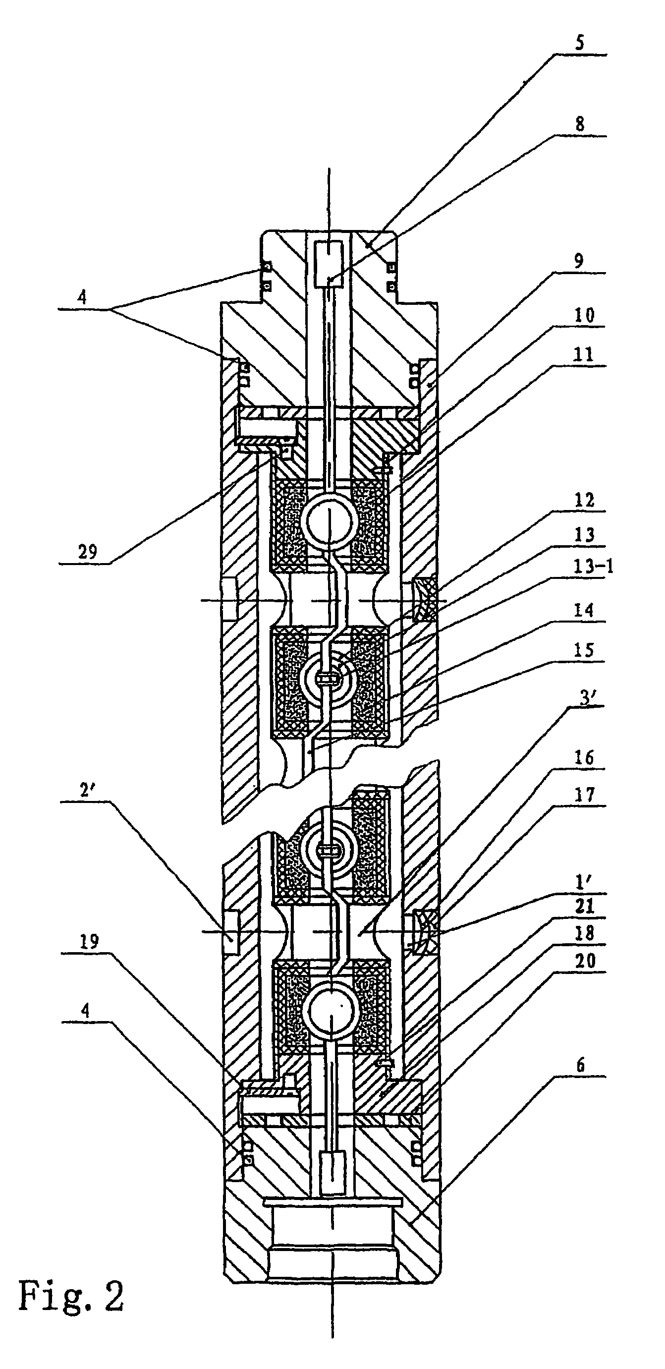
[0053]In FIG. 1 and FIG. 2, the embodiment is constructed through connecting together a two-section perforating gun 1, a gun top 2, an igniting unit 3, a rubber gasket 4, an upper connector 5, a lower connector 6, a gun bottom 7 and a booster 8. An upper end of the top most section perforating gun 1 is connected with the gun top 2 and its lower end is connected with an upper end of the lower section perforating gun 1 through the lower connector 6 and the upper connector 5, the rubber gasket 4 is installed between the upper connector 5 and the lower connector 6 as well as between the gun top 2 and the perforating gun 1, the lower end of the lowermost section perforating gun 1 is connected with the gun bottom 7, the detonator igniting unit 3 is installed in the gu...


PUM


Abstract

The invention relates to a perforating device comprising one or more perforating gun (1) installed in a perforating body (9), a perforating gun head (2) in the uppermost end of the perforating body (9), a perforating gun base (7) in the lowermost end of the perforating body (9) and a detonating device (3) installed inside or outside the perforating head (2), in which a charge frame (10, 22) is installed inside of the perforating body (9). A plurality of perforator unit connected each other by a detonating cord (15) are provided on the charge frame (10, 22). Every perforator unit comprises an explosive box (11) in a charge socket, a charge (13) in charge housing (12) and energy-bearing media (14). Moreover, an energy-bearing media sleeve (28) is provided outside of the perforating device. The perforating device is easy to manufacture with low cost and can be used securely in the operation.

Description

FIELD OF THE INVENTION[0001]The invention relates to an apparatus for producing petroleum, gas, water and the dissolvable or soluble materials or minerals from wells, in particular to a device for energy concentration and jet perforating.BACKGROUND OF THE INVENTION[0002]The Chinese utility model patent No. 97242235.8 under the title of “a high-energy combined overbalance high density double jet perforating device for oil-gas wells” employs a cylindrical powder sleeve or a solid-propellant sleeve, any of which has several charge sockets distributed in its different lengths and different phases and has a detonating cord hole used for inserting a detonating cord while a charge is mounted in the corresponding charge socket. The structure of the powder sleeve or the solid-propellant sleeve is difficult to realize through a certain manufacturing process, moreover before the down hole operation in the oil field it is required to cut the composite solid-propellant sleeve, which decreases th...

Claims


Application Information

Patent Timeline
IPC IPC(8): E21B43/117E21B43/116
CPCE21B43/116
Inventor ZHANG, XIZHANG, TINGHAN
Owner XIAN TONGYUAN PETROTECH
Why Eureka
Try Eureka