Air compressor mounted on a compressor tank

a technology of air compressor and compressor tank, which is applied in the direction of positive displacement liquid engine, piston pump, liquid fuel engine, etc., can solve the problems of air intake that is often noisy and still quite a bit of noise from the intake valv

Inactive Publication Date: 2006-01-31
DEVILBISS AIR POWER COMPANY
View PDF27 Cites 42 Cited by
  • Summary
  • Abstract
  • Description
  • Claims
  • Application Information

AI Technical Summary

Benefits of technology

[0011]The present invention is directed to an oilless air compressor having a high speed electric motor that drives an air compressor pump. The electric motor and the air compressor pump are mounted on a common frame with a pulley gear reduction system between the two. A single shroud is mounted around the motor and the pump. The shroud is a clamshell configuration having top and bottom halves. The top includes multiple openings for controls and gauges for the air compressor. The controls and gauges are mounted in the bottom of the shroud and alignment guides are used in the top to properly position the top relative to the bottom so that the two clamshell halves are fitted together and the openings are precisely aligned with the gauges and controls. By mounting the controls and gauges on the shroud, proper alignment of the controls and gauges is provided.

Problems solved by technology

This air intake is often noisy, so many prior art air compressors include short pump head air intake mufflers.
Although these air intake mufflers work well for their intended purpose, there is still quite a bit of noise from the intake valves that is audible to people in the air compressor's immediate surroundings.

Method used


Image

  • Air compressor mounted on a compressor tank
  • Air compressor mounted on a compressor tank
  • Air compressor mounted on a compressor tank

Examples


Embodiment Construction

[0022]In the following description, various aspects of the present invention will be described. For purposes of explanation, specific configurations and details are set forth in order to provide a thorough understanding of the present invention. However, it will also be apparent to one skilled in the art that the present invention may be practiced without the specific details. Furthermore, well-known features may be omitted or simplified in order not to obscure the present invention. In addition, to the extent that orientations of the invention are described, such as “top,”“bottom,”“front,”“rear,” and the like, the orientations are to aid the reader in understanding the invention, and are not meant to be limiting.

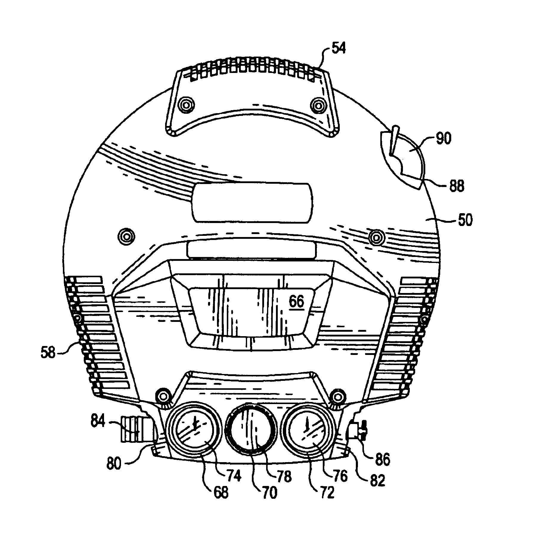
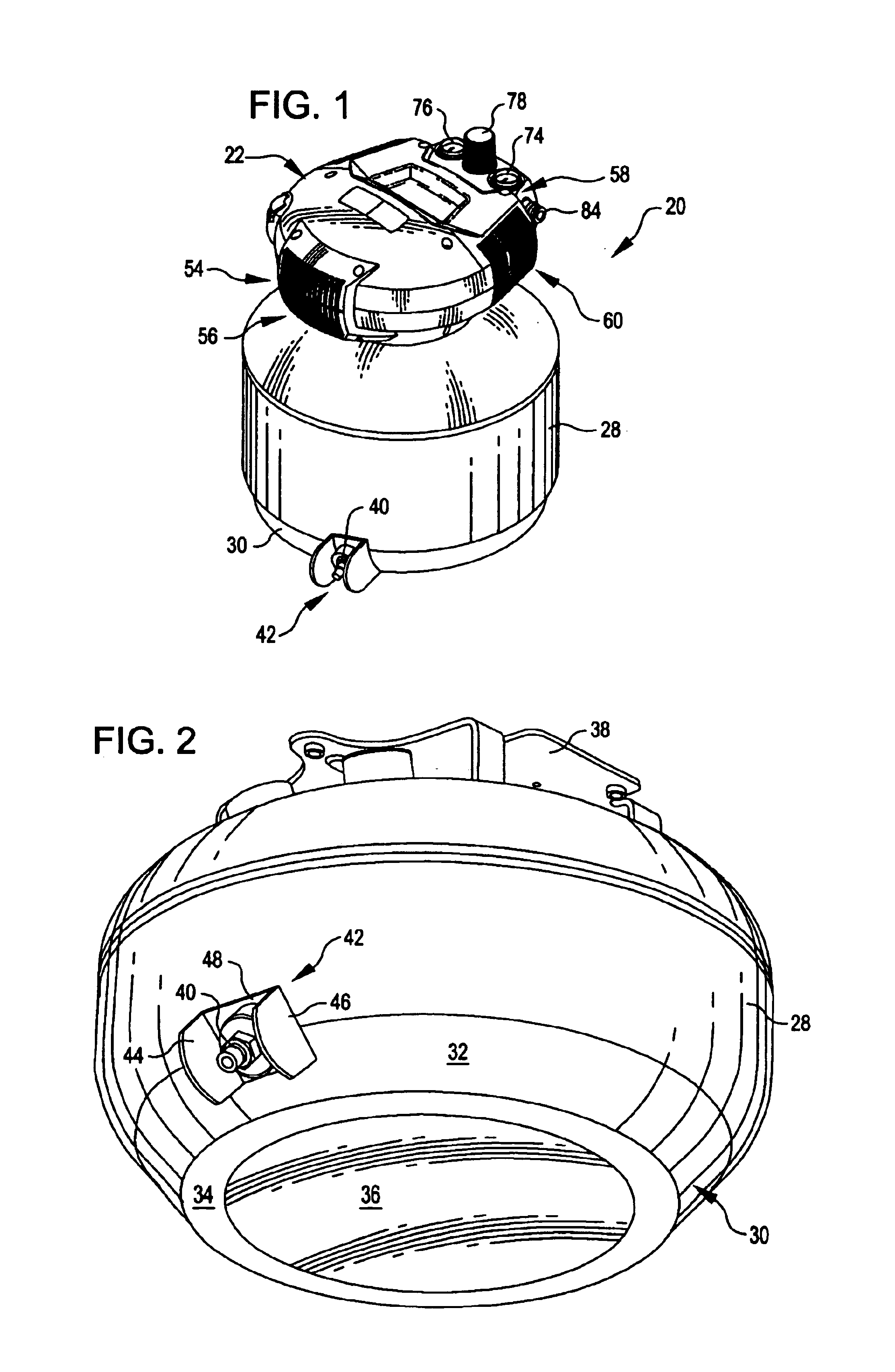
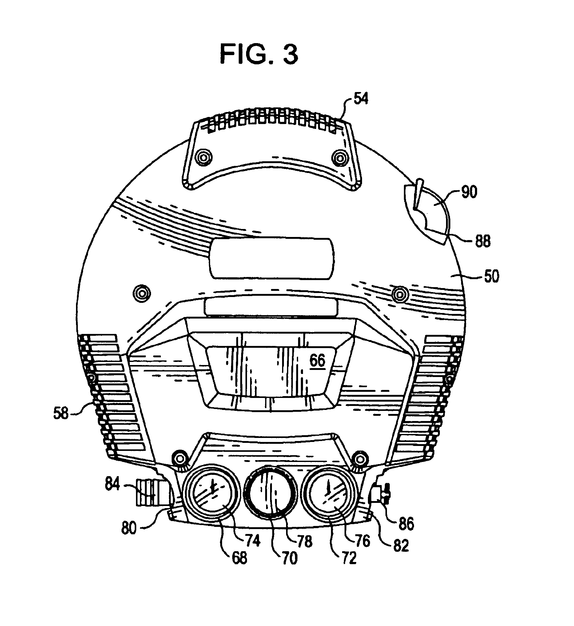
[0023]Referring now to the drawings, in which like reference numerals represent like parts throughout the several views, FIG. 1 shows an air compressor 20 embodying the present invention. Briefly described, the air compressor 20 provides at least five novel aspects. First, ...


PUM


Abstract

An air compressor having a cooling fan that cools both a pump and an electric motor. Baffle compress air against the top of the motor, causing it to break up and flow around fours sides of the motor and through the motor. The pump includes an elongate intake tube or muffler that attenuates pump intake noise. A compressor tank for the air compressor includes a roll cage for protecting a condensate valve for the compressor tank. The compressor tank includes a rim base formed on the bottom of the compressor tank that permits the compressor tank to rest on a surface without additional supports or legs. Controls and gauges are mounted in the bottom clamshell piece, and openings on a top fit around the controls and gauges. The top and the bottom are aligned with guides so that the controls and gauges may be properly aligned with the openings.

Description

FIELD OF THE INVENTION[0001]The present invention relates generally to power tools, and more particularly to air compressors.BACKGROUND OF THE INVENTION[0002]Air compressors are becoming commonplace in home workshops. In general, an air compressor, or an air pump, is a machine that decreases the volume and increases the pressure of a quantity of air by mechanical means. Air thus compressed possesses great potential energy, because when the external pressure is removed, the air expands rapidly. The controlled expansive force of compressed air is used in many ways and provides the motive force for air motors and tools, including pneumatic hammers, air drills, sandblasting machines, and paint sprayers.[0003]A conventional home workshop air compressor includes a storage tank for compressed air, and a prime mover mounted on the compressor tank for compressing the air flowing into the compressor tank. The prime mover may be a gas engine or an electric motor, but most conventional home wor...

Claims


Application Information

Patent Timeline
Patent Type & Authority Patents(United States)
IPC IPC(8): F04B23/14F04B39/06
CPCF04B39/066
Inventor BECKMAN, KURTKOPEL, ANDREWKLIMEK, PAULDAVIDSON, JAN
Owner DEVILBISS AIR POWER COMPANY
Why Eureka
Try Eureka