Ground fault detection device

Inactive Publication Date: 2006-01-31
HONDA MOTOR CO LTD
View PDF5 Cites 50 Cited by
  • Summary
  • Abstract
  • Description
  • Claims
  • Application Information

AI Technical Summary

Benefits of technology

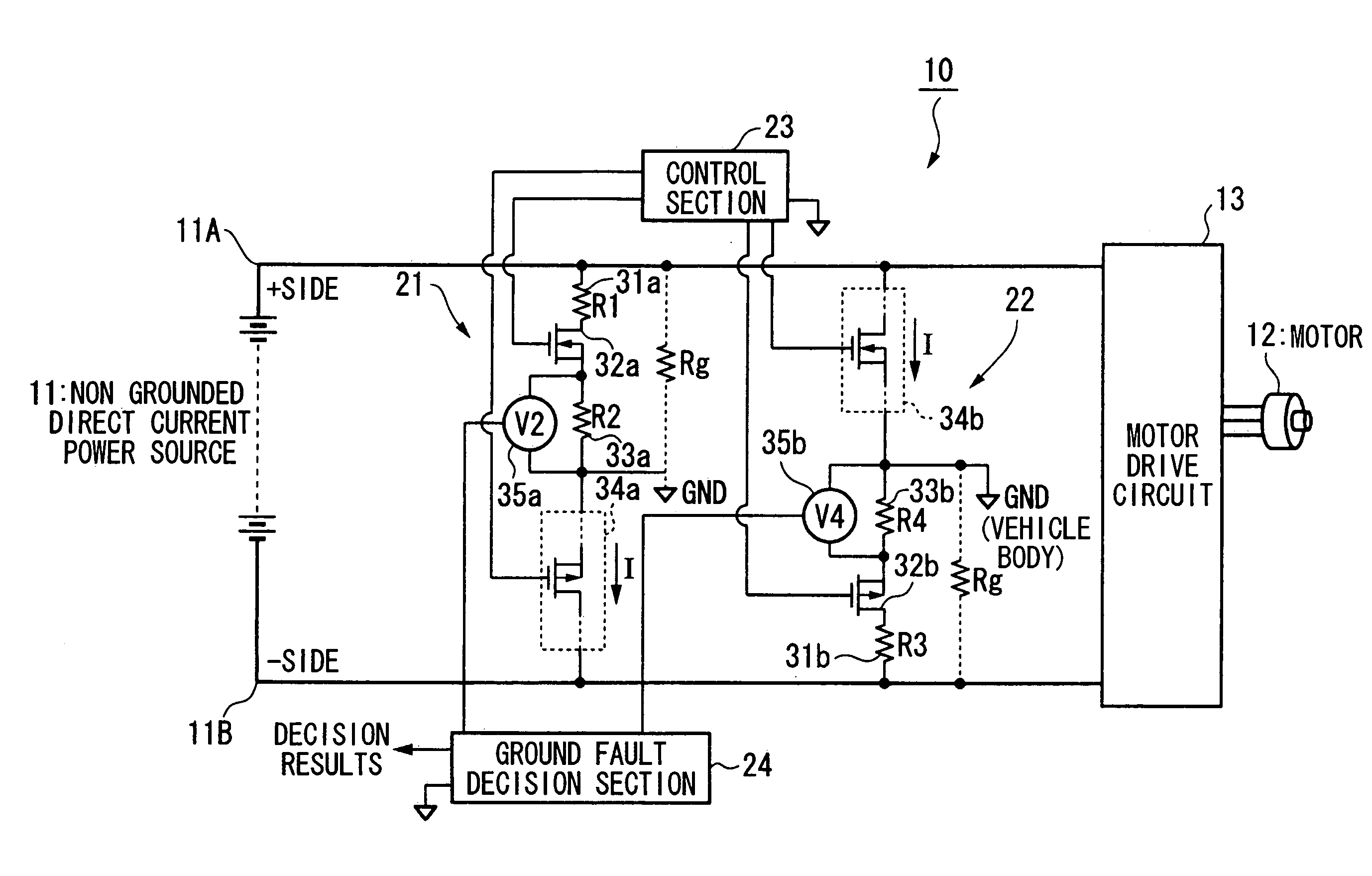
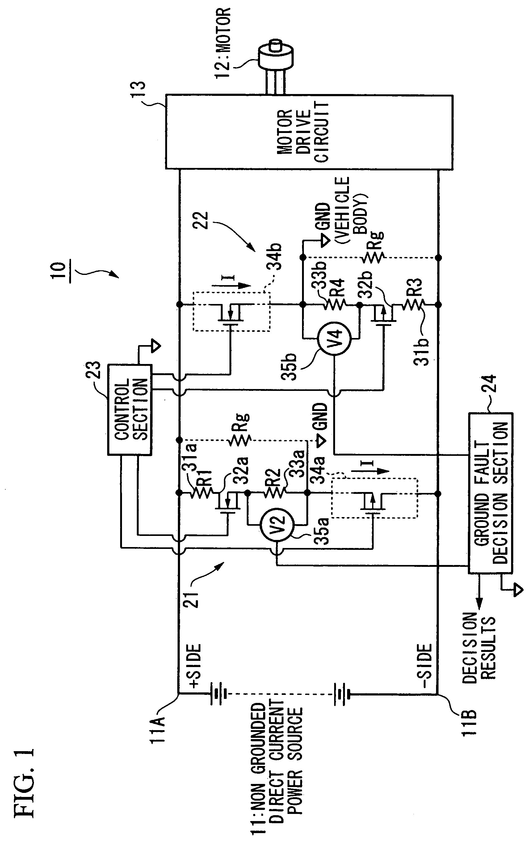
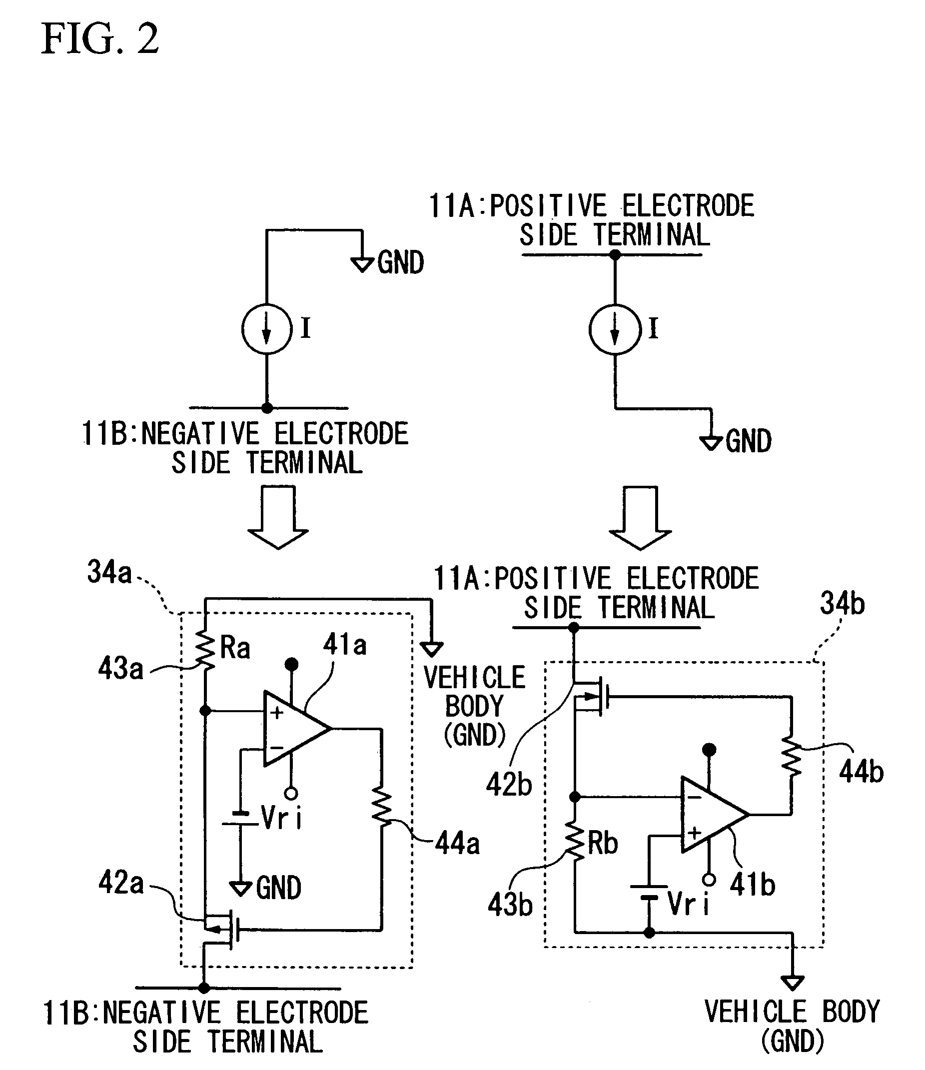
[0010]According to a ground fault detection device of the above described construction, the terminal voltage which is present between both the ends of the ground fault detection resistor changes according to the resistance value of this ground fault detection resistor and according to the current value of the current which flows through this ground fault detection resistor, and it does not depend upon the output voltage of the direct current power source. In other words, if no ground fault is occurring, the predetermined current which is outputted from the constant current source flows through the ground fault detection resistor, while, when a ground fault which exhibits an appropriate ground fault resistance occurs, this predetermined current which is outputted from the constant current source is divided between the ground fault detection resistor and the ground fault resistance. Due to this, it is possible to determined that a ground fault has occurred, if the terminal voltage which is present between the two ends of the ground fault detection resistor has become smaller than a predetermined voltage value according to, for example, the resistance value of the g

Problems solved by technology

However, in the above described conventional ground fault detection method, there have been the drawbacks that it is necessary to provide a voltage detection section for detecting the power source voltage of the high voltage direct current power source, and also that a structure for co

Method used


Image

  • Ground fault detection device
  • Ground fault detection device
  • Ground fault detection device

Examples


Embodiment Construction

[0023]In the following, preferred embodiments of the ground fault detection device of the present invention will be described with reference to the appended drawings.

[0024]The ground fault detection device 10 according to this preferred embodiment of the present invention is mounted to a vehicle such as, for example, a fuel cell vehicle or a hybrid vehicle or the like, and it detects ground faults, in other words the presence or absence of insulation breakdown, occurring upon the positive electrode side or upon the negative electrode side of a non-earthed direct current power source 11 (hereinafter simply termed a direct current power source) which is electrically insulated from the vehicle chassis, which, for example, is earthed.

[0025]Here, the direct current power source 11 is a capacitor in which a plurality of capacitor cells such as, for example, electric double layered condensers or electrolytic condensers or the like are connected in series, or is a battery in which a plurali...


PUM


Abstract

A control section sets a positive side switching element of a positive side detection section and a negative side switching element of a negative side detection section to ON, thus outputting an ON signal. When the switching elements are set ON, a predetermined current outputted from a positive side constant current source and a negative side constant current source, or a portion of this current, flows through detection resistors. A ground fault decision section decides whether a ground fault has occurred in the positive or the negative side of a direct current power source, based upon the value of an output voltage detected by a positive side voltage detector, or upon the value of an output voltage detected by a negative side voltage detector. Ground faults are accurately detected with a simple structure.

Description

BACKGROUND OF THE INVENTION[0001]1. Field of the Invention[0002]The present invention relates to a ground fault detection device which, for example, is carried upon a vehicle or the like.[0003]Priority is claimed on Japanese Patent Application No. 2003-123641, filed Apr. 28, 2003, the content of which is incorporated herein by reference.[0004]2. Description of Related Art[0005]Conventionally, there is, for example, a known method of ground fault detection, in which the presence or absence of occurrence of a ground fault at an appropriate position of a direct current circuit which is equipped with a high voltage direct current power source is detected by selectively switchover connecting a current detector or a voltage detector for ground fault detection to the anode side and the cathode side of the direct current circuit (for example, Japanese Patent Application Unexamined Publication No. 4-12616).[0006]Furthermore, in this type of ground fault detection method, there is a known det...

Claims


Application Information

Patent Timeline
IPC IPC(8): G01R31/02B60L3/00G01R31/36H02H3/16
CPCB60L3/0023G01R31/36G01R31/024B60L3/0069G01R31/52
Inventor NOMOTO, YOSHIKAZUTSURUMI, TAKAFUMIARIYOSHI, TOSHIAKIYANO, MITSUTERU
Owner HONDA MOTOR CO LTD
Why Eureka
Try Eureka