Temperature-stabilized oscillator circuit

a technology of oscillator circuit and temperature stability, which is applied in the direction of oscillator generator, pulse technique, pulse generator, etc., can solve the problems of large production expenditure and high cost associated with low and achieve low noise 1/f , high temperature stability of oscillator frequency

Inactive Publication Date: 2006-01-31
INFINEON TECH AG
View PDF11 Cites 37 Cited by
  • Summary
  • Abstract
  • Description
  • Claims
  • Application Information

AI Technical Summary

Benefits of technology

[0011]It is an object of the invention to provide an oscillator circuit by means of which the temperature coefficient of the oscillator frequency can be set to a predetermined value and by means of which, in particular, a high temperature stability of the oscillator frequency, an operating voltage suppression and a low 1 / f noise are achieved.

Problems solved by technology

However, what is disadvantageous about such compensation of temperature fluctuations is that technologically governed variations both of the temperature coefficients and of the absolute values of the resistors used bring about only a low temperature stability of the oscillator frequency.
What is common to these known measures is a large production outlay with the high costs associated therewith.

Method used


Image

  • Temperature-stabilized oscillator circuit
  • Temperature-stabilized oscillator circuit
  • Temperature-stabilized oscillator circuit

Examples


Embodiment Construction

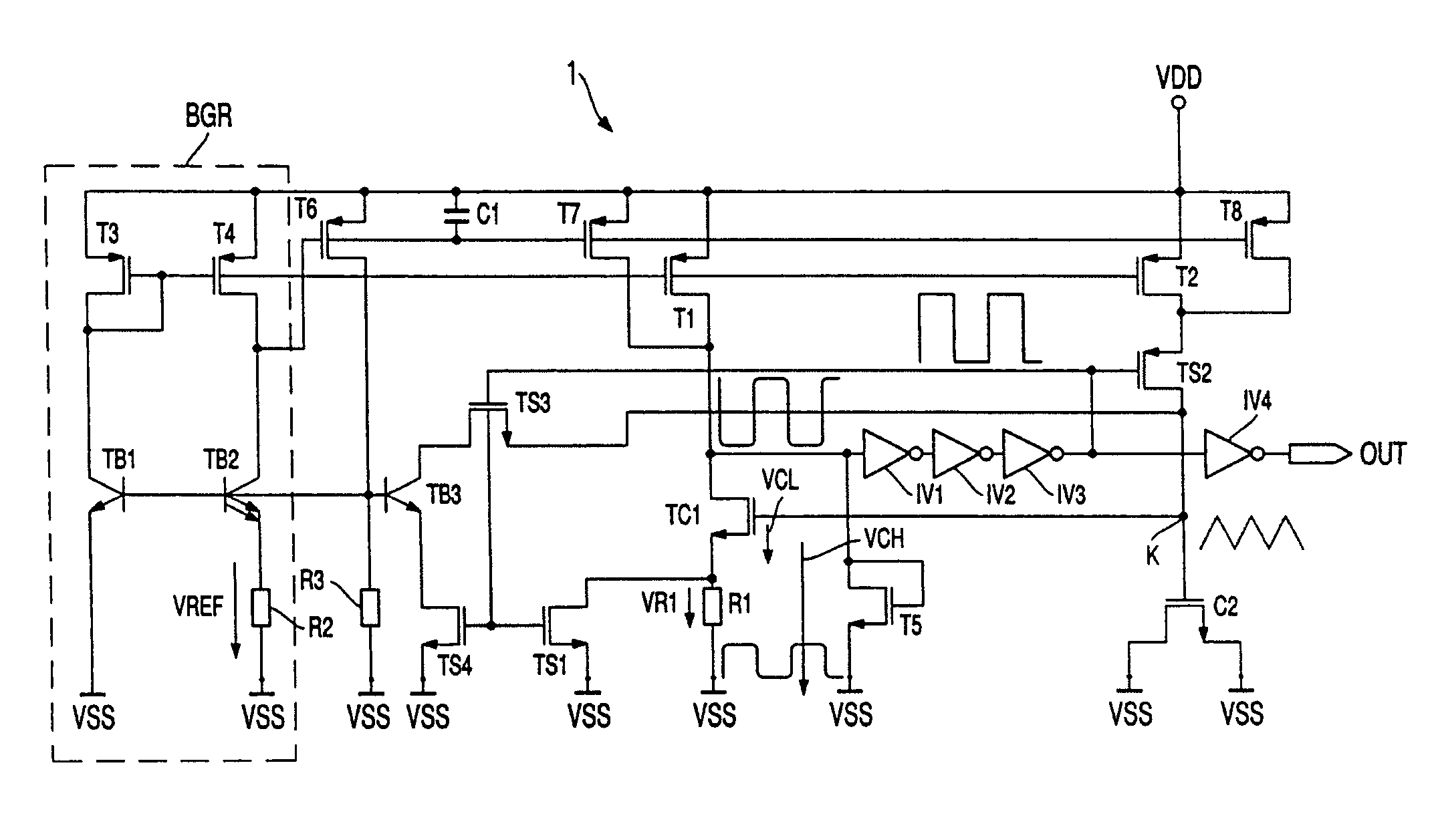
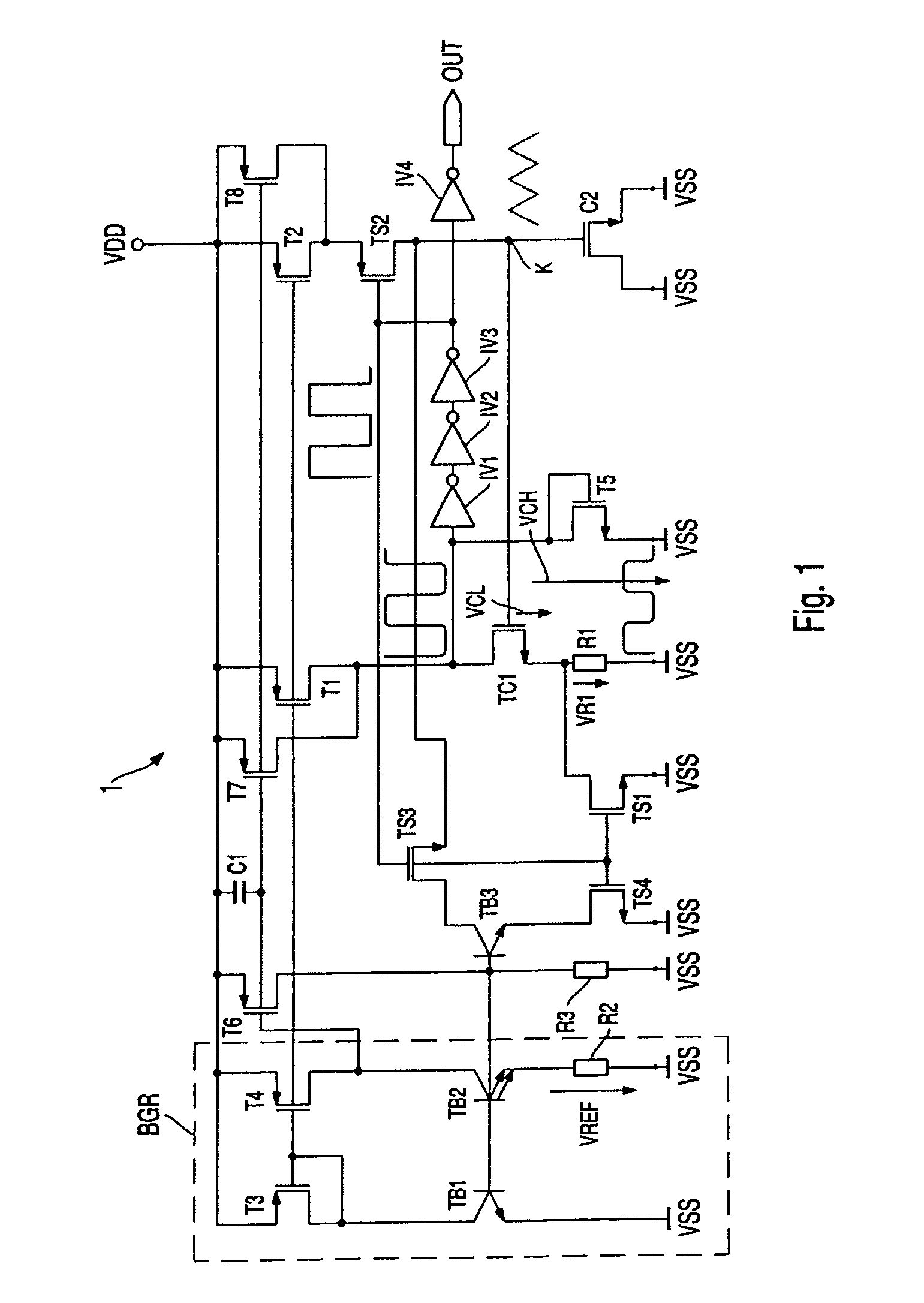
[0036]FIG. 1 illustrates a circuit diagram of a temperature-stabilized oscillator circuit 1 as a first exemplary embodiment of the invention. The oscillator circuit 1 has a charge storage device C2, which is connected on the one hand to a common fixed potential, in particular a ground VSS, and on the other hand to a node K. The gate terminal of a MOS transistor TC1 is furthermore connected to the node K. The node K may be fed by an upward-integration circuit branch, which connects the node K to a supply voltage VDD via the drain-source paths of MOS transistors TS2 and T2. A further circuit branch formed by the drain-source path of a MOS transistor TS3, the collector-emitter path of a bipolar transistor TB3 and also the drain-source path of a MOS transistor TS4 serves for drawing current from the node K. This circuit branch conducts the drawn current away to ground VSS.

[0037]The drain-source path of the MOS transistor TC1 is connected by a comparator / reference voltage circuit branch ...


PUM


Abstract

Temperature-stabilized oscillator circuit A temperature-stabilized oscillator circuit (1) comprises a first part with a first temperature dependence and a second part with a second temperature dependence, which is different from the first temperature dependence. A charge storage device (C2), a controllable upward-integration current source (T2) for charging the charge storage device (C2), a controllable downward-integration current source (TB3) for discharging the charge storage device (C2) and two resistors (R2, R1) having the same temperature coefficients are contained in each case in one of the two parts.

Description

CROSS REFERENCE TO RELATED APPLICATION[0001]This application is a continuation of copending International Application No. PCT / DE02 / 03907 filed Oct. 15, 2002 which designates the United States, and claims priority to German application no. 101 57 292.1 filed Nov. 22, 2001.TECHNICAL FIELD OF THE INVENTION[0002]The present invention generally relates to an oscillator circuit based on cyclic charging and discharging of a charge storage device. In particular the invention relates to an oscillator circuit which provides an operating clock for apparatuses in standby operation.DESCRIPTION OF RELATED ART AND BACKGROUND OF THE INVENTION[0003]Integrated circuits generally obtain their operating clock during normal operation from a crystal oscillator. During standby operation, integrated circuits are often supplied with the operator clock by an oscillator circuit or a phase shifter oscillator circuit, since these circuits are distinguished by a low current consumption.[0004]Oscillator circuits ...

Claims


Application Information

Patent Timeline
Patent Type & Authority Patents(United States)
IPC IPC(8): H03B5/24H03K3/011H03K3/0231H03K3/354
CPCH03K3/011H03K3/0231H03K3/354
Inventor HOLLINGER, WERNERMOTZ, MARIO
Owner INFINEON TECH AG
Why Eureka
Try Eureka