Image processing apparatus, a reader controller, and a method for controlling the reader controller

a technology of image processing apparatus and reader controller, which is applied in the direction of digital output to print units, instruments, electrographic processes, etc., can solve the problems of increasing production costs, inability to obtain copy output in real time, and inconvenient operation, so as to achieve high processing speed and efficient execution. , the effect of high processing speed

Inactive Publication Date: 2006-01-31
CANON KK
View PDF11 Cites 11 Cited by
  • Summary
  • Abstract
  • Description
  • Claims
  • Application Information

AI Technical Summary

Benefits of technology

[0183]Since the reader controller is provided between the printer controller and the engine controller so as to be communicatable with each of these controllers, and analyzes a command provided from the printer controller to the engine controller and performs control for the execution of the command by the engine controller in accordance with the result of the analysis, it is possible to realize a copying function having a high processing speed without causing a large amount of change in the hardware and software in the configuration of a printer function caused by the addition of an image reading device in order to add a copying function to the printer function, and to transmit the command provided from the printer controller to the engine controller while maintaining consistency in the operation.
[0184]When the printer controller controls the engine controller, the printer controller performs control so as to delay the execution of a command causing a change in the load of the engine controller and to instantaneously execute a command capable of obtaining the status of the engine controller, from among commands provided from the reader controller to the engine controller. Hence, it is possible to operate a command processing sequence while maintaining consistency.
[0185]When the reader controller controls the engine controller, the reader controller performs control so as to first make a command causing a change in the load of the engine controller to wait within the reader controller and to delay the execution of the command by transmitting a response corresponding to the command to the printer controller, and to instantaneously execute a command capable of obtaining the status of the engine controller, from among commands provided from the printer controller to the engine controller. Hence, it is possible to operate a command processing sequence while maintaining consistency.
[0186]The reader controller is provided between the printer controller and the engine controller so as to be communicatable with each of these controllers. When a set-state confirming command for confirming the set state of the engine controller is provided from the printer controller, the reader controller retrieves the location of the status corresponding to the set-state confirming command, reads the corresponding status from the location, and transmits the read status to the printer controller. Hence, it is possible to realize a copying function having a high processing speed without causing a large amount of change in the hardware and software in the configuration of a printer function caused by the addition of an image reading device for adding a copying function to the printer function, and to prevent a decrease in the communication efficiency due to the provision of the reader controller between the printer controller and the engine controller.
[0187]When the location of the status corresponding to the set-state confirming command is within the reader controller, the reader controller transmits the status corresponding to the set-state confirming command to the printer controller via the first communication means. When the location of the status corresponding to the set-state confirming command is within the engine controller, the reader controller transmits a command equivalent to the set-state confirming command to the engine controller via the second communication means. In response to that command, the engine controller transmits a status equivalent to the status transmitted via the second transmission means to the printer controller via the first communication means. Hence, communication relating to the confirmation of the set state can be efficiently executed.
[0188]Since the reader controller is provided between the printer controller and the engine controller so as to be communicatable with each of these controllers, and the reader controller rewrites the status for each of the printer controller and the reader controller every time the setting of the operation of the engine controller is performed and stores the obtained status, it is possible to realize a copying function having a high processing speed without causing a large amount of change in the hardware and software in the configuration of a printer function caused by the addition of an image reading device for adding a copying function to the printer function, and to reduce the amount of communication processing relating to the setting of operations.

Problems solved by technology

Accordingly, a considerable time is required for transferring the image data output from the image reading device 2501 to the printer controller 2103, and therefore a copy output cannot be obtained in a real time.
In the composite apparatus shown in FIG. 22, since it is necessary to newly provide the I / F 2601 for connecting the controller unit 2602 to the reader unit 2502, it is necessary to greatly change the hardware and software in order to provide a composite apparatus having a printer function and a copying function based on a conventional laser-beam printer, thereby providing a surplus time for the development of the apparatus, and a possibility of greatly increasing the production cost.

Method used


Image

  • Image processing apparatus, a reader controller, and a method for controlling the reader controller
  • Image processing apparatus, a reader controller, and a method for controlling the reader controller
  • Image processing apparatus, a reader controller, and a method for controlling the reader controller

Examples


Embodiment Construction

[0051]A preferred embodiment of the present invention will now be described with reference to the drawings.

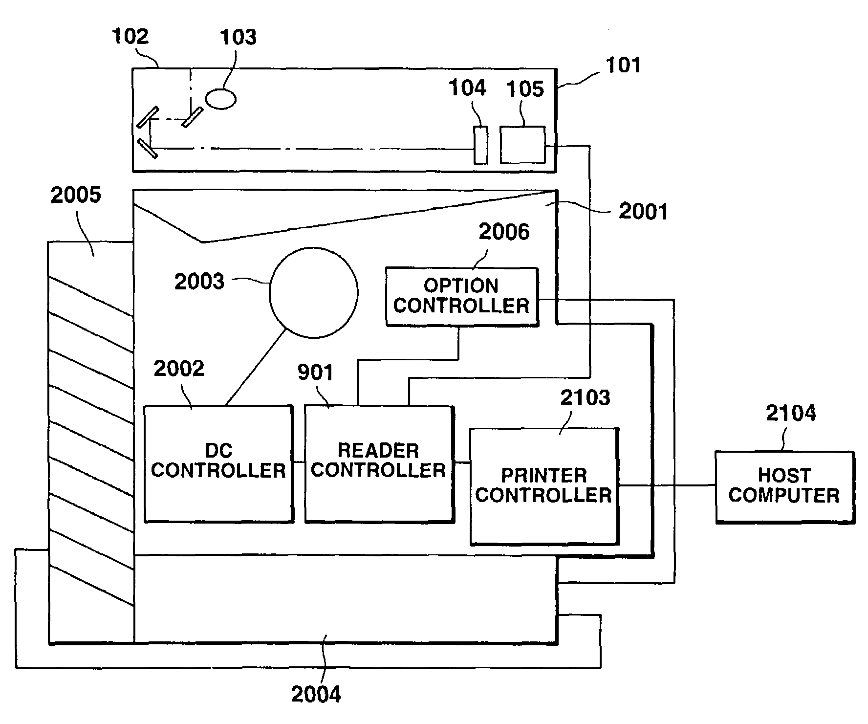
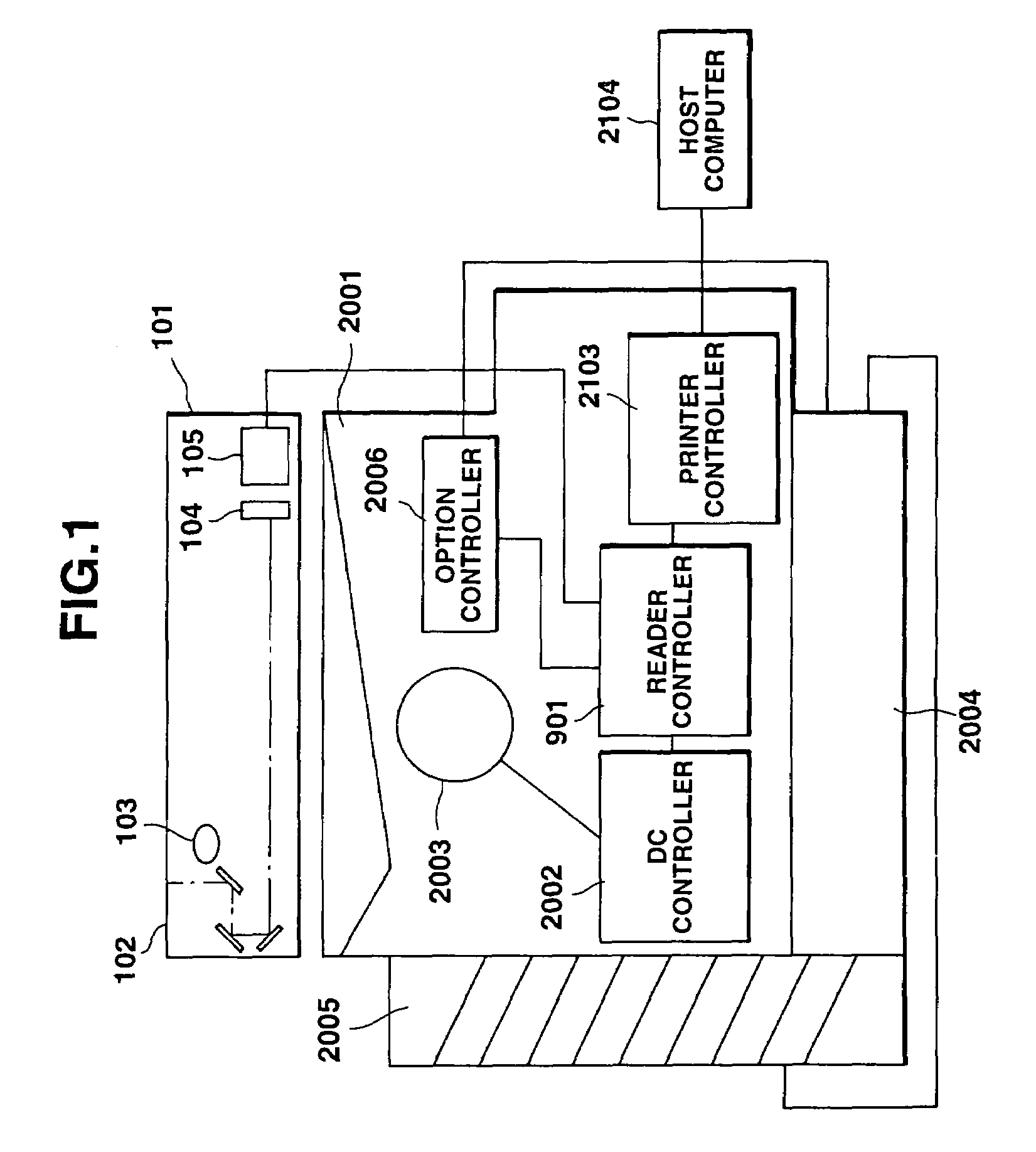
[0052]First, a description will be provided of an image forming mechanism within a laser-beam printer to which the present invention is applied, with reference to FIG. 15. FIG. 15 is a diagram illustrating the configuration of the image forming mechanism within the laser-beam printer to which the present invention is applied.

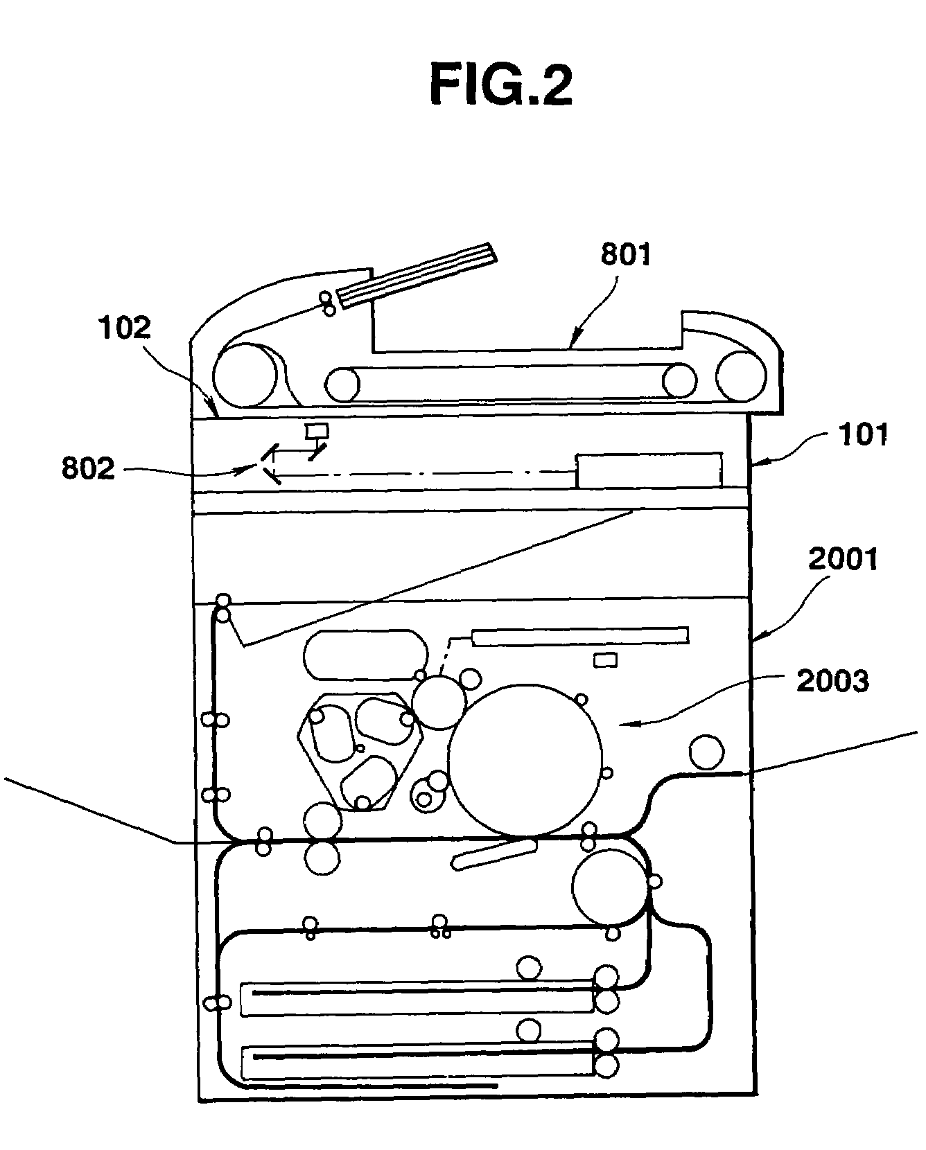
[0053]The image forming mechanism includes a mechanism for forming an electrostatic latent image on a photosensitive drum by laser-beam scanning, a mechanism for developing the electrostatic latent image, an optical processing mechanism for transferring the latent image onto a printing sheet, a fixing processing mechanism for fixing a toner image transferred onto the printing sheet, a printing-sheet feeding processing mechanism, and a printing-sheet conveying processing mechanism.

[0054]More specifically, as shown in FIG. 15, an optical processing mechanism ...


PUM


Abstract

An image processing apparatus includes an engine controller for controlling an image forming mechanism for forming an image on a sheet based on image data, a printer controller for forming image data from printing data transferred from an external apparatus, for transmitting the image data to the engine controller, and for transmitting a command for setting an operation of the engine controller to the engine controller, and a reader controller for controlling an original-reading device for outputting image data by reading an image of an original, and for transmitting the image data output from the original-reading device to the engine controller. The reader controller is provided between the printer controller and the engine controller so as to be communicatable with each of the printer controller and the engine controller, and controls the acquisition of a right to use the engine controller with the printer controller.

Description

[0001]This application is a divisional of U.S. patent application Ser. No. 08 / 901,286, filed Jul. 29, 1997 now U.S. Pat. No. 6,023,559.BACKGROUND OF THE INVENTION[0002]1. Field of the Invention[0003]This invention relates to an image processing apparatus having a printer function and a copying function, a reader controller mounted in such an apparatus, and a method for controlling the reader controller.[0004]2. Description of the Related Art[0005]In general, printing apparatuses include ink-jet printers, thermal transfer printers, electrophotographic printers and the like. The electrophotographic printers include, for example, laser-beam printers.[0006]A description will now be provided of the configuration and the state of use of a laser-beam printer with reference to FIGS. 19 and 20. FIG. 19 is a schematic block diagram illustrating the configuration of a conventional laser-beam printer. FIG. 20 is a diagram illustrating the state of use of the laser-beam printer shown in FIG. 19....

Claims


Application Information

Patent Timeline
Patent Type & Authority Patents(United States)
IPC IPC(8): G06F15/00G03G15/20H04N1/00H04N1/32
CPCH04N1/00236H04N1/32561H04N1/00238H04N1/00204H04N2201/0082H04N2201/0081
Inventor KOHTANI, HIDETOARAI, KOJINONAKA, TAKASHI
Owner CANON KK
Why Eureka
Try Eureka