Using an external spiral servo writer to write spiral reference patterns to a disk to facilitate writing product servo bursts to the disk

a technology of spiral reference pattern and spiral reference pattern, which is applied in the field of disk drives, can solve the problems of inability to accurately inability to write spiral reference pattern to disk drive, and inability to meet the requirements of clean room environment, so as to facilitate the use of a conventional servo algorithm and increase the accuracy of head position error

Inactive Publication Date: 2006-01-31
WESTERN DIGITAL TECH INC
View PDF20 Cites 138 Cited by
  • Summary
  • Abstract
  • Description
  • Claims
  • Application Information

AI Technical Summary

Benefits of technology

[0010]In another embodiment, a radial length of a product servo burst defines a data track, the product servo bursts form a plurality of servo wedges, and a slope of each spiral reference pattern equals approximately one data track per servo wedge. In yet another embodiment, a slope of each spiral reference pattern is selected so that each spiral reference pattern is written over at least twenty revolutions of the disk to increase the accuracy of the head position error generated from the reference servo bursts.
[00

Problems solved by technology

However, external servo writers are expensive and require a clean room environment so that a head positioning pin can be inserted into the head disk assembly (HDA) without contaminating the disk.
Thus, external servo writers have become an expensive bottleneck in the disk drive manufacturing process.
However, the calibration process will inevitably exhibit some degree of error and the dynamics of the disk drive will change between seeks inducing errors in the radial position of the spiral tracks.
Dynamic errors which degrade the spiral tracks written during an open loop seek include vibration of the

Method used


Image

  • Using an external spiral servo writer to write spiral reference patterns to a disk to facilitate writing product servo bursts to the disk
  • Using an external spiral servo writer to write spiral reference patterns to a disk to facilitate writing product servo bursts to the disk
  • Using an external spiral servo writer to write spiral reference patterns to a disk to facilitate writing product servo bursts to the disk

Examples


Embodiment Construction

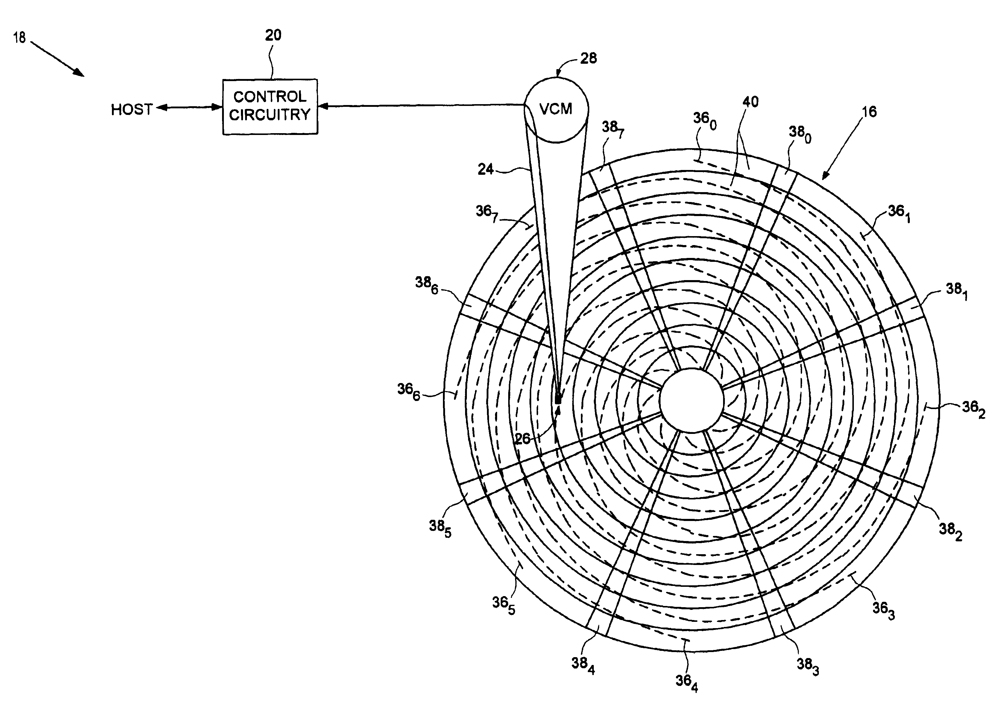
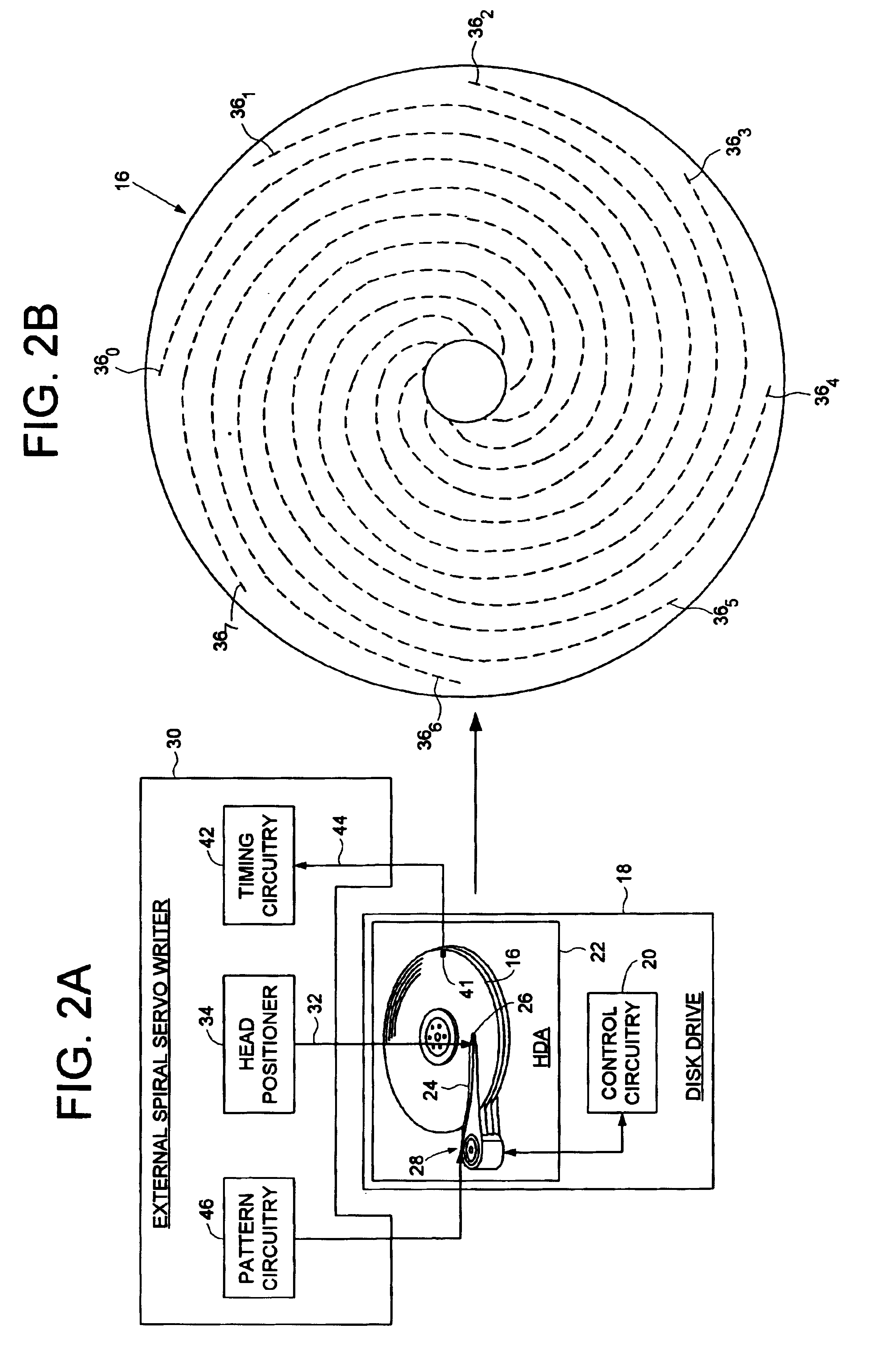
[0019]FIG. 2A illustrates a method of writing product servo bursts to a disk 16 of a disk drive 18. The disk drive 18 comprises control circuitry 20 and a head disk assembly (HDA) 22 comprising the disk 16, an actuator arm 24, a head 26 connected to a distal end of the actuator arm 24, and a voice coil motor 28 for rotating the actuator arm 24 about a pivot to position the head 26 radially over the disk 16. A head positioning pin 32 of an external spiral servo writer 30 is inserted into the HDA 22, the head positioning pin 32 for engaging the actuator arm 24. The external spiral servo writer 30 comprises head positioning mechanics 34 used to derive a radial location of the head 26. The head positioning pin 32 is actuated in response to the radial location of the head 26 in a closed loop system in order to position the head 26 radially over the disk 16 while writing a plurality of reference servo bursts to the disk along a plurality of substantially spiral paths to form a plurality o...


PUM


Abstract

A method of writing product servo bursts to a disk in a disk drive is disclosed. An external spiral servo writer comprising a head positioning pin and head positioning mechanics periodically writes a plurality of reference servo bursts in a plurality of spiral reference patterns to the disk. The reference servo bursts in the spiral reference patterns are processed to write product servo bursts to the disk. In one embodiment control circuitry within the disk drive processes the reference servo bursts to self-servo write the disk drive, and in another embodiment an external product servo writer processes the reference servo bursts to write the product servo bursts to the disk. In one embodiment, a slope of each spiral reference pattern is selected so that each spiral reference pattern is written over at least twenty revolutions of the disk to increase the accuracy of the head position error generated from the reference servo bursts.

Description

BACKGROUND OF THE INVENTION[0001]1. Field of the Invention[0002]The present invention relates to disk drives for computer systems. More particularly, the present invention relates to using an external spiral servo writer to write spiral reference patterns to a disk to facilitate writing product servo bursts to the disk.[0003]2. Description of the Prior Art[0004]When manufacturing a disk drive, servo sectors 20-27 are written to a disk 4 which define a plurality of radially-spaced, concentric data tracks 6 as shown in the prior art disk format of FIG. 1. Each servo sector (e.g.; servo sector 24) comprises a preamble 8 for synchronizing gain control and timing recovery, a sync mark 10 for synchronizing to a data field 12 comprising coarse head positioning information such as a track number, and product servo bursts 14 which provide fine head positioning information. During normal operation the product servo bursts 14 are processed by the disk drive in order to maintain a head over a c...

Claims


Application Information

Patent Timeline
IPC IPC(8): G11B21/02
CPCG11B5/59633
Inventor AGARWAL, VINAY K.CLOKE, ROBERT L.
Owner WESTERN DIGITAL TECH INC
Why Eureka
Try Eureka