
Methods and apparatus for removing compression artifacts in video sequences

a technology of compression artifacts and video sequences, applied in the field of filtering, can solve the problems of computational intensive techniques used to achieve these tasks and introduce undesirable blurring effects, and achieve the effect of reducing noise and increasing amplitud

Inactive Publication Date: 2006-01-31
ALTERA CORP
View PDF15 Cites 44 Cited by
  • Summary
  • Abstract
  • Description
  • Claims
  • Application Information

AI Technical Summary

Benefits of technology

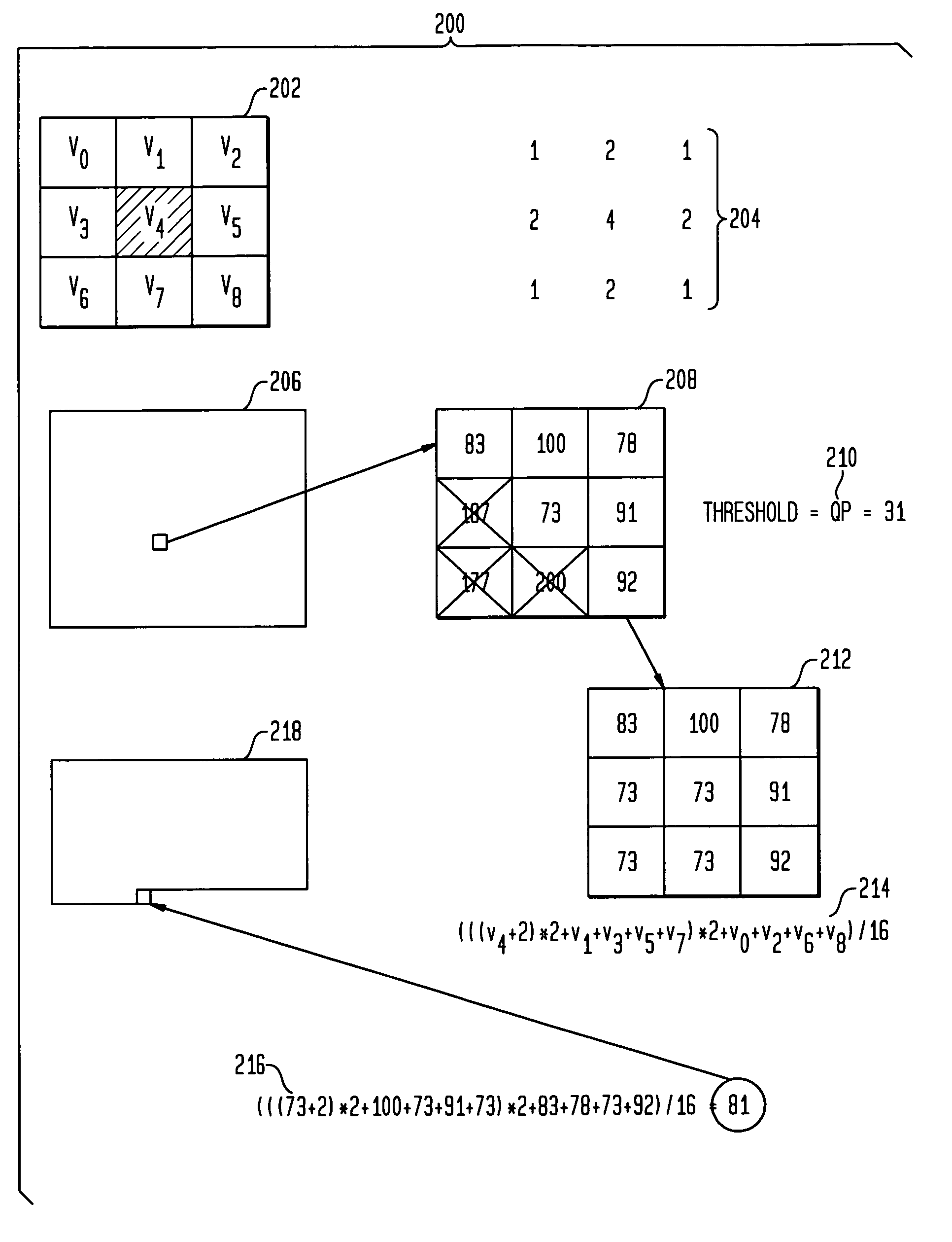
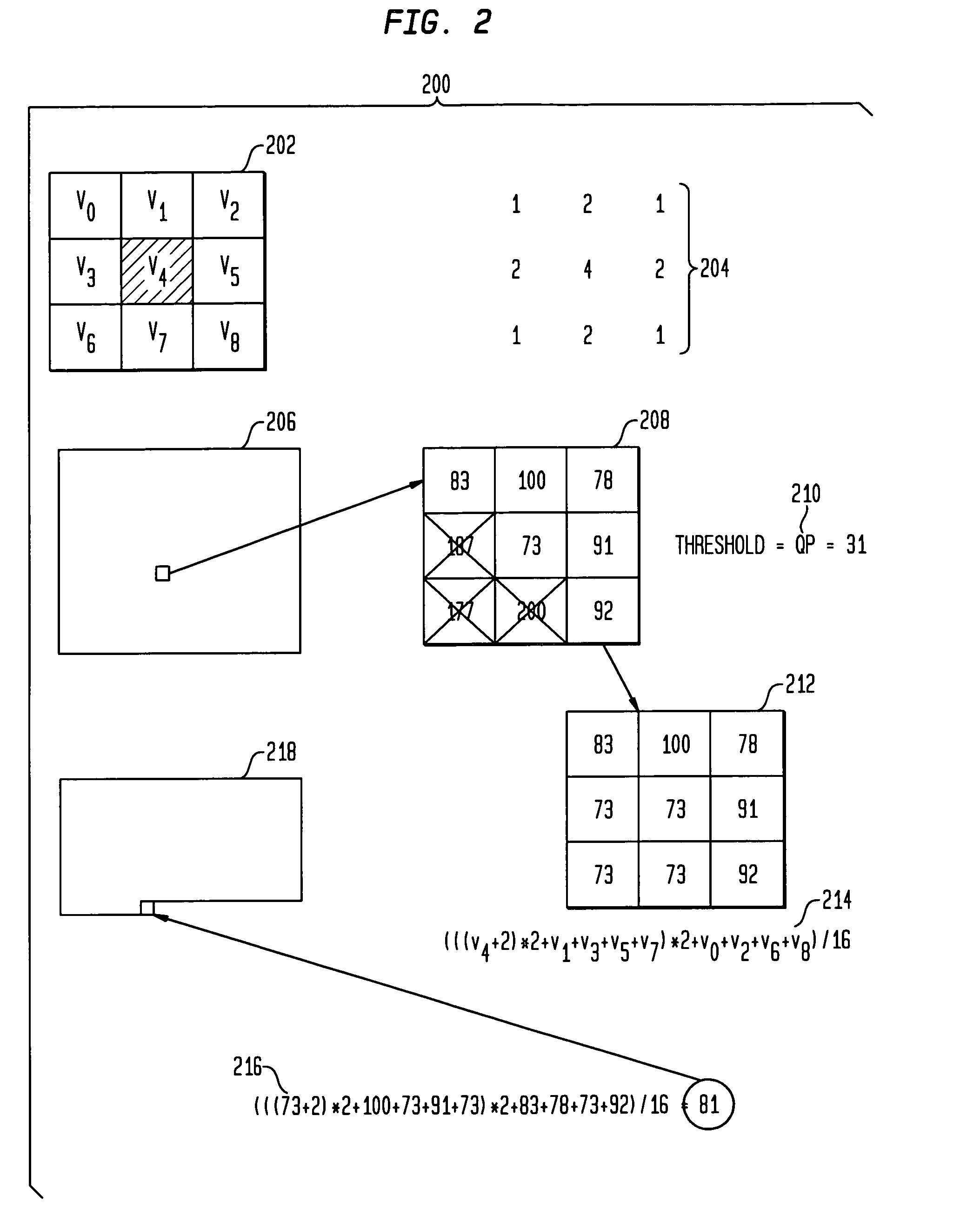
[0005]The present invention advantageously provides methods and apparatus for removing ringing artifacts from video data. A deringing filter in accordance with the present invention preserves real image edges in a video frame, while smoothing out the interiors of objects. In one aspect, a 9-tap low-pass filter is applied to an adaptive processing window. The filter window is initialized with the values in a 3×3 mask centered on the position whose output is computed. Then, all values that are significantly different from the central value are replaced with the central value. The deringing filter varies between a 3×3 low-pass filter and an identity filter, depending on how much the central value differs from its surrounding values. The deringing method of the present invention detects image edges and applies a filter along these edges to eliminate the noise. The decision between edge and non-edge block borders relies on the assumption that real borders have a higher amplitude than edges produced by the quantization of DCT coefficients. A deblocking filter in accordance with the present invention may also be suitably used in conjunction with the deringing filter.

Problems solved by technology

The techniques used to achieve these tasks are computationally intensive and usually require high speed processors to be able to run in real time.
However, this type of filtering may introduce undesirable blurring effects when applied to pixels which belong to real image edges.

Method used


Image

  • Methods and apparatus for removing compression artifacts in video sequences
  • Methods and apparatus for removing compression artifacts in video sequences
  • Methods and apparatus for removing compression artifacts in video sequences

Examples


Embodiment Construction

[0018]The present invention now will be described more fully with reference to the accompanying drawings, in which several presently preferred embodiments of the invention are shown. This invention may, however, be embodied in various forms and should not be construed as limited to the embodiments set forth herein. Rather, these embodiments are provided so that this disclosure will be thorough and complete, and will fully convey the scope of the invention to those skilled in the art.

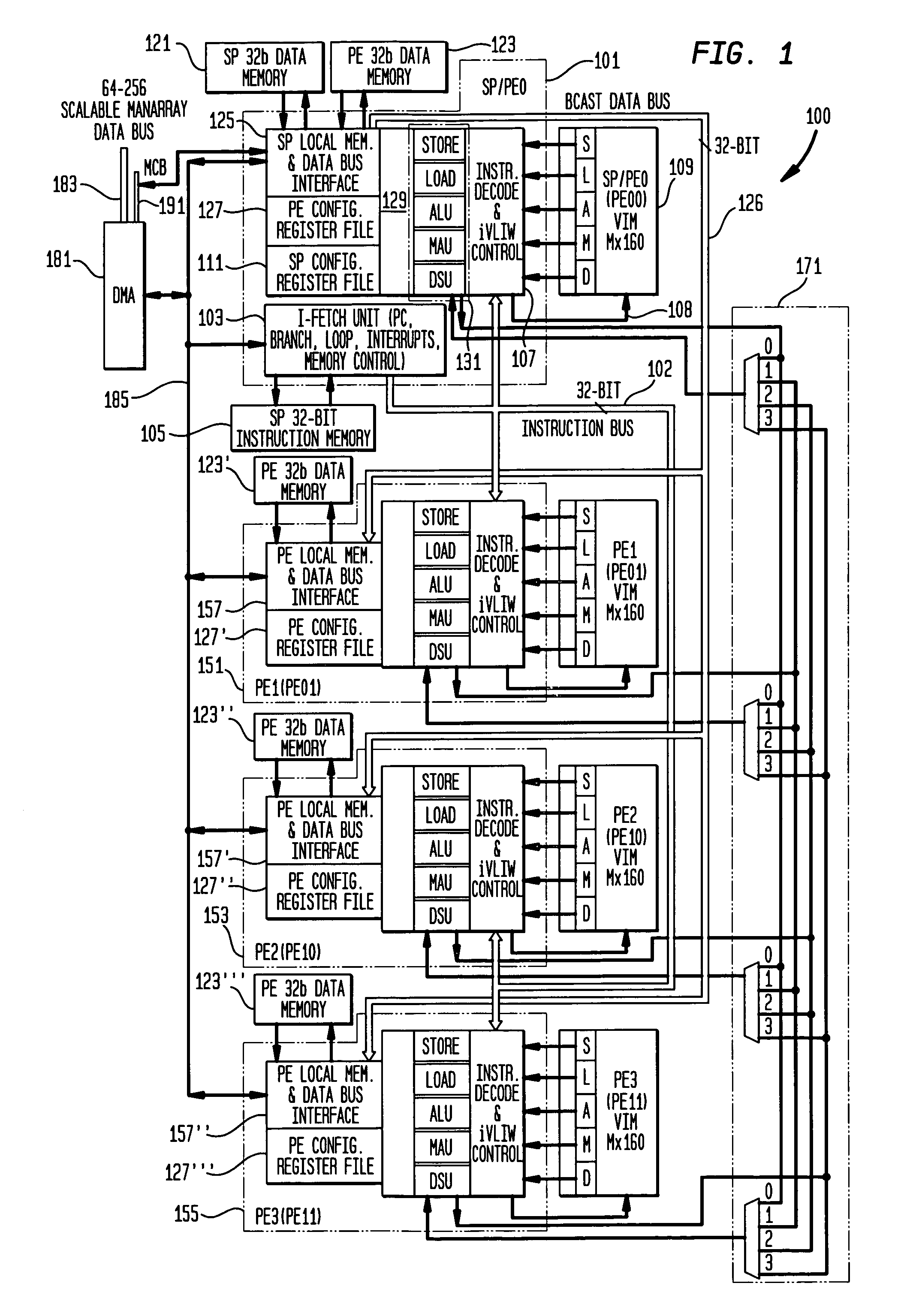
[0019]Further details of a presently preferred ManArray core, architecture, and instructions for use in conjunction with the present invention are found in:

[0020]U.S. patent application Ser. No. 08 / 885,310 filed Jun. 30, 1997, now U.S. Pat. No. 6,023,753;

[0021]U.S. patent application Ser. No. 08 / 949,122 filed Oct. 10, 1997, now U.S. Pat. No. 6,167,502;

[0022]U.S. patent application Ser. No. 09 / 169,256 filed Oct. 9, 1998, now U.S. Pat. No. 6,167,501;

[0023]U.S. patent application Ser. No. 09 / 1 69,255 filed ...


PUM


Abstract

Techniques for removing ringing artifacts from video data. A deringing filter in accordance with the present invention preserves real image edges in a video frame, while smoothing out the interiors of objects. In one aspect, a 9-tap low-pass filter is applied to an adaptive processing window. The filter window is initialized with the values in a 3×3 mask centered on the position whose output is computed. Then all values that are very different from the central one are replaced with the central value. The deringing filter varies between 3×3 low-pass and identity, depending on how much the central value differs from its surrounding ones. A deblocking filter in accordance may also be suitably used in conjunction with the deringing filter.

Description

[0001]The present application claims the benefit of U.S. Provisional Application Ser. No. 60 / 288,965 filed May 4, 2001, and entitled “Methods and Apparatus for Removing Compression Artifacts in Video Sequences” which is incorporated herein by reference in its entirety.FIELD OF THE INVENTION[0002]The present invention relates generally to improvements in video processing. More specifically, the present invention relates to filters which provide for improved visual quality in video decoding.BACKGROUND OF THE INVENTION[0003]In low bit rate video coding, the quantization of discrete cosine transform (DCT) coefficients produces well known artifacts in decoded images. The best known artifacts are the blocking effect and the ringing effect. Signal adaptive filters are generally used to remove these artifacts, while preserving details which belong to the image. Deblocking and deringing are two video post-processing techniques used to remove coding artifacts and improve the visual quality wh...

Claims


Application Information

Patent Timeline
IPC IPC(8): G06K9/56H04N5/14H04N5/21H04N7/26H04N7/30
CPCH04N5/14H04N19/86H04N5/21
Inventor PETRESCU, DOINA
Owner ALTERA CORP
Learn More