Mobile radio communication terminal

Inactive Publication Date: 2006-01-31
FUJITSU TOSHIBA MOBILE COMM LTD
View PDF10 Cites 46 Cited by
  • Summary
  • Abstract
  • Description
  • Claims
  • Application Information

AI Technical Summary

Benefits of technology

[0016]According to the third aspect of the invention, the radio communication operation is performed so that the operation according to the second radio communication mode does not overlap the operation according to the first radio communication mode in time. Thus the power supply circuit does not have to simultaneously feed power to both the radio circuit for the first radio communica

Problems solved by technology

However, a terminal of this type conventionally used or devised has a disadvantage that such a terminal has large power consumption because it is generally equipped with circ

Method used


Image

  • Mobile radio communication terminal
  • Mobile radio communication terminal
  • Mobile radio communication terminal

Examples


first embodiment

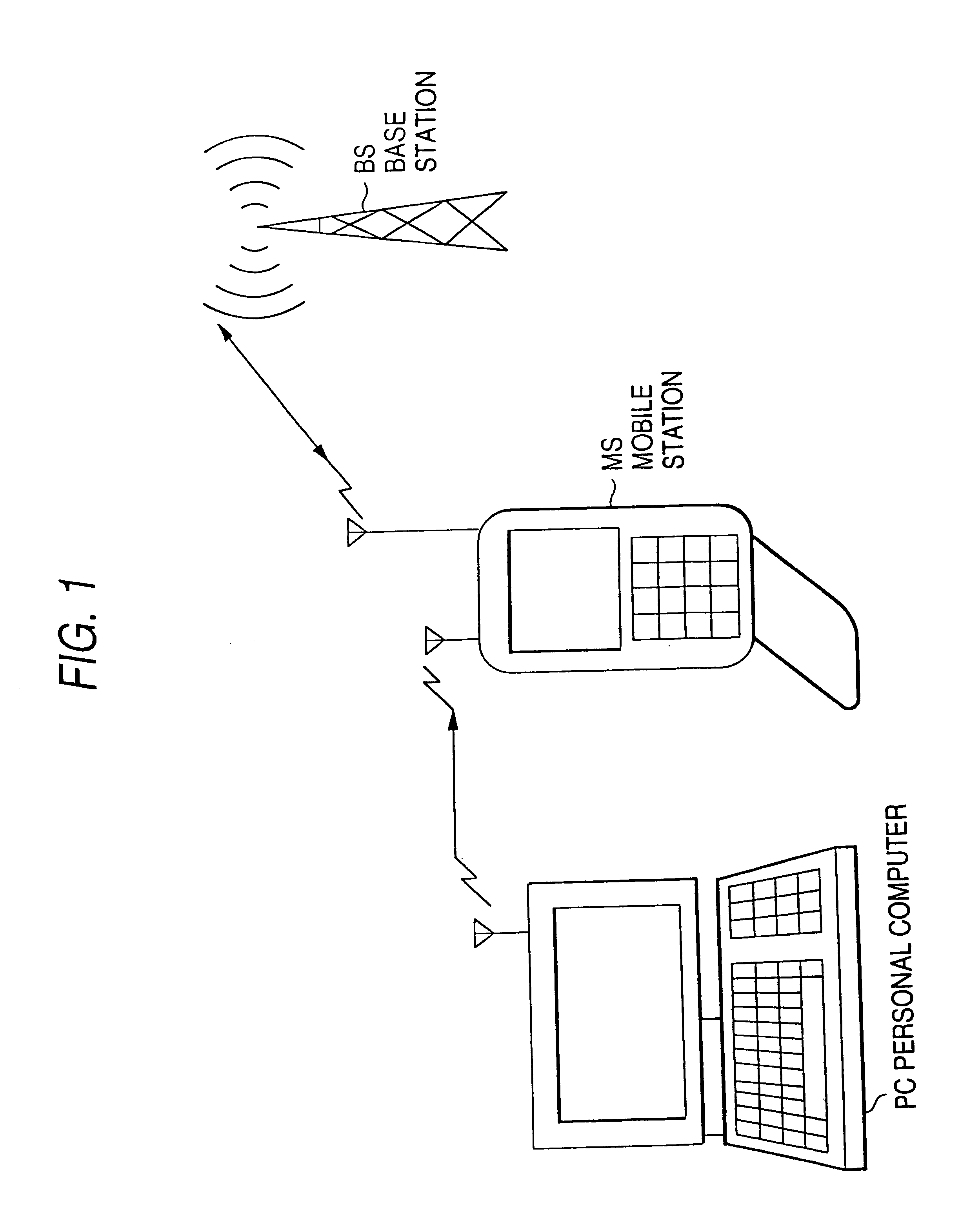
[0031]FIG. 1 is a schematic block diagram of an embodiment of a mobile communication system using a mobile radio communication terminal according to the invention.

[0032]A mobile station MS is equipped with the radio communication feature via the W-CDMA (Wideband-Code Division Multiple Access) system and the radio communication feature via the BT (Bluetooth) system. The W-CDMA (Wideband-Code Division Multiple Access) system enables high-speed, large-capacity multimedia mobile communications by using a bandwidth of, for example, 5 MHz in the 2 GHz band. This system establishes synchronization with base stations (BSs) distributed in the service area before it initiates communications. The CDMA system is used as a radio access system between a base station and a mobile station. Three systems, DS-FDD (Direct Sequence-Frequency Division Duplex), MC-FDD (Multi Carrier-Frequency Division Duplex), and TDD (Time Division Duplex), are selectively used as an upstream and downstream multiplex co...

second embodiment

[0063]The second embodiment according to the invention takes advantage of the fact that the wait operation period according to the W-CDMA system depends on the timing of frames sent from the base station while the wait operation period according to the BT system can be arbitrarily set by the originating apparatus. The second embodiment shortens the operation time of the CPU of the main control circuit and reduces the power consumption, by setting the wait operation period according to the BT system so that the period coincides with the wait operation period according to the W-CDMA system.

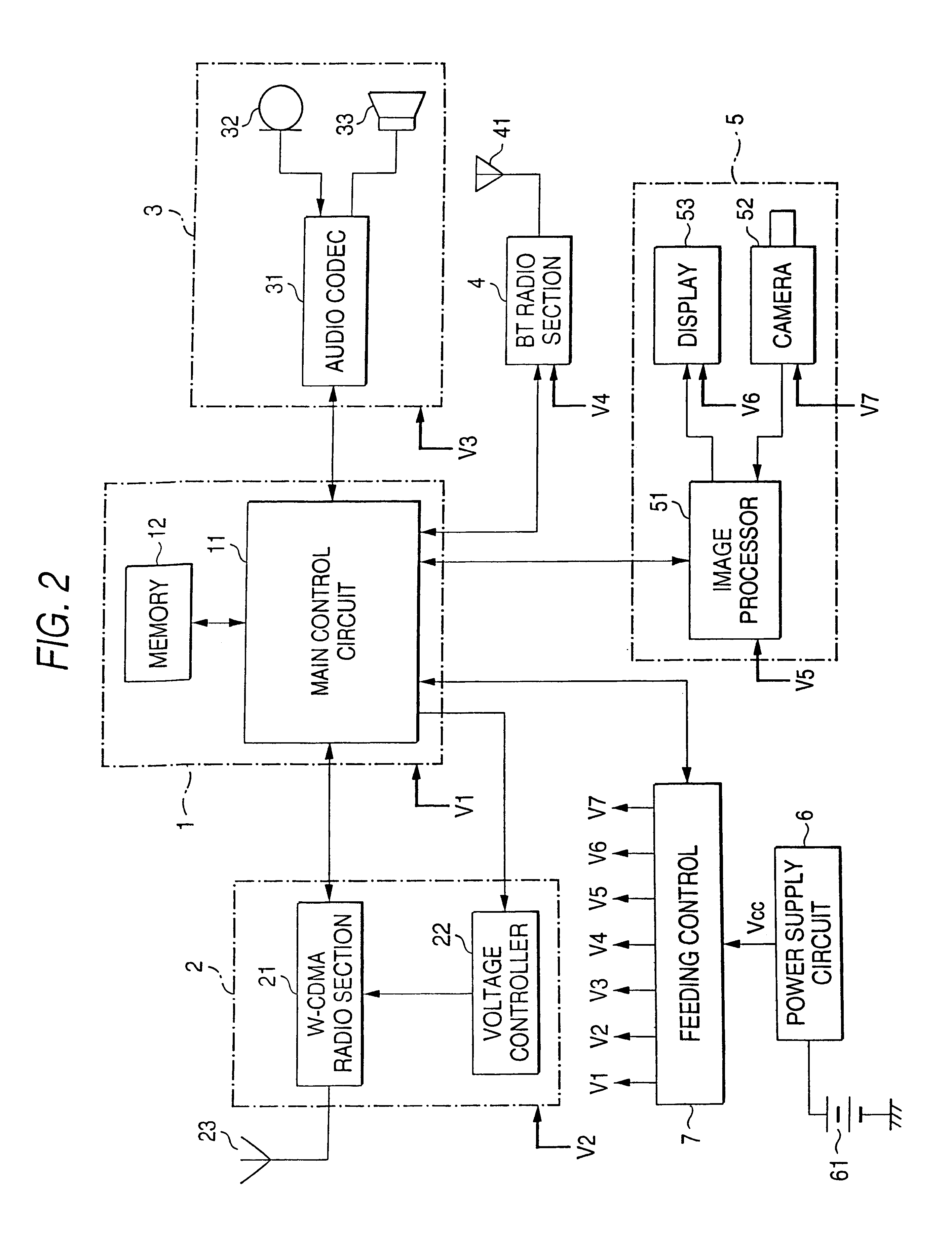
[0064]FIG. 8 is a circuit block diagram of a mobile station MS showing the second embodiment of a mobile radio communication terminal according to the present invention. In FIG. 8, the same portions as those in FIG. 2 are given the same reference numerals / signs and details thereof are not discussed here.

[0065]The main control circuit additionally comprises wait period setting control means 111. The ...

third embodiment

[0068]In the third embodiment of the invention, the sending slot period and the receiving slot period according to the BT system are separately set from the sending slot period and the receiving slot period according to the W-CDMA system respectively in the operation mode in which radio communications via the W-CDMA system is executed in parallel with radio communications via the BT system, thus preventing simultaneous operation of the W-CDMA radio section 21 and the BT radio section 4 to make unnecessary the increase in the capacity of the power supply circuit 6.

[0069]FIG. 11 is a circuit block diagram of a mobile station MS showing the third embodiment of a mobile radio communication terminal according to the present invention. In FIG. 11, the same portions as those in FIG. 2 and FIG. 8 are given the same reference numerals / signs and details there of are not discussed here.

[0070]The main control circuit additionally comprises communication period setting control means 112. The com...


PUM


Abstract

In a mobile radio communication terminal includes a feeding controller 7 with a feeding control table. In the feeding control table 7 is stored the on/off state of the power to each circuit in correspondence with all operation modes for the apparatus. In case an operation mode is reported from the main control circuit 11 prior to the operation, output Vcc of the power supply circuit 6 is fed to the minimum circuits necessary for execution of the operation mode according to the operation mode and information stored in the feeding control table 7, and power to the remaining circuits is shut off or reduced.

Description

BACKGROUND OF THE INVENTION[0001]1. Field of the Invention[0002]The present invention relates to a mobile radio communication terminal such as a mobile station and a portable information terminal, and in particular, to a mobile radio communication terminal for selectively using a plurality of radio communication systems to perform radio communication.[0003]2. Description of the Related Art[0004]In recent years, with the development of radio communication technologies and an increase in communication needs, a variety of mobile radio communication terminals have been developed and used. Among these terminals are terminals which allow communication by selectively using a plurality of radio communication systems.[0005]For example, a terminal which selectively uses the TDMA (Time Division Multiple Access) system and the AMPS system, one type of the FDMA (Advanced Mobile Phone System) system, a terminal which selectively uses the PDC (Personal Digital Cellular) system, one type of the TDM...

Claims


Application Information

Patent Timeline
IPC IPC(8): H04M1/00H04B7/26H04L12/28H04M1/73H04W52/02H04W72/02H04W76/02H04W88/02H04W88/06
CPCH04W52/0261H04W88/06H04W52/0274H04M1/7253H04W72/02H04M1/72412Y02D30/70
Inventor ITO, KOICHIYAMAGUCHI, KENTOKUOKAMOTO, SEIICHI
Owner FUJITSU TOSHIBA MOBILE COMM LTD
Why Eureka
Try Eureka