Location measurement process for radio-frequency badges

a technology of radio frequency badges and measurement processes, applied in direction finders using radio waves, instruments, data switching networks, etc., can solve the problems of inability to provide the actual 3d location of the person or object, system infrared-based, inconvenient operation, etc., and achieve the effect of simple radio frequency and minimal overhead costs

Inactive Publication Date: 2006-01-31
MICROSOFT TECH LICENSING LLC
View PDF26 Cites 21 Cited by
  • Summary
  • Abstract
  • Description
  • Claims
  • Application Information

AI Technical Summary

Benefits of technology

[0015]The present invention is directed toward a system and process for determining the location of persons and objects in an environment that overcomes the limitations of existing location systems by utilizing existing infrastructure to minimize overhead costs and by employing a compact, simple radio frequency (RF) transmitter as a badge.
[0018]The location of each TX transmitting a TX ID message is computed using the badge hit table data. The computed location is then used to update an entity location table of a geometric model database. The geometric model database contains information concerning the descriptions of the locations of people, devices, places, and objects in the world. The entity location table is essentially a list of entities and the TX identifier of a TX that is associated with each entity, as well as the location of the entity if known. An entity is simply a person, object or a collection of persons and objects, and the location of the entity is the location determined for the associated TX. The process for computing the locations of the TXs, which is referred to as the sensor fusion process, can be performed by the centralized computer's badge hit database. This is particularly efficient if the geometric model database resides on the centralized computer. However, if the geometric model database runs on a computer other than the centralized computer, then it may be more efficient to transfer the raw badge hit table data and have the sensor fusion process performed by the geometric model database.
[0020]The screening phase begins by, for each entry of the badge hit table, determining whether the signal strength value of the entry exceeds a signal strength threshold. This signal strength threshold is chosen to correspond to the signal level a RX would measure if the transmitting TX was within a prescribed distance (e.g., 1–2 meters) of the RX. This improves the accuracy of the location determining procedure as will become clear shortly. When it is found that the signal strength of the entry equals or exceeds the signal strength threshold, then the entry is deemed to have passed the thresholding test. Otherwise, the entry is ignored for purposes of computing the location of the associated TX. For each entry passing the thresholding test, it is next determined if a time table has been established for the associated TX. If not, one is created. The time tables log the hit time of each entry associated with a particular TX that passed the thresholding test. To this end, the hit time of the entry under consideration is logged into the time table assigned to the associated TX, regardless of whether the table was just created or existed previously. It is next ascertained whether the difference in the hit time of the entry under consideration and that of any of the previously logged hit times (if any) in the time table assigned to the TX associated with the entry, fall within a prescribed time period. If none of the computed differences fall within the period, then the entry is deemed to have cleared a time conflict resolution test. If, however, any of the computed differences do fall within the period, then it is assumed the entries involved are attributable to the same or a redundant TX transmission that gives no new location information. Given this assumption, just one of them is selected for further processing to determine the location of the TX. The entry selected is then deemed to have cleared the time conflict resolution test. Those entries clearing the time conflict resolution test are used to determine the location of the TX, as will be described shortly. However, first it is noted that the entry selected among those assumed to be attributable to the same or a redundant TX transmission, can be selected in a number of ways. For example, the entry could be selected at random, or the entry having the earliest hit time could be selected. However, in tested embodiments of the sensor fusion process, the entry having the most recent hit time was chosen.

Problems solved by technology

These types of systems do not provide the actual 3D location of the person or object carrying the badge.
In addition, these systems, being infrared-based, are susceptible to interference from spurious infrared emissions from such sources as fluorescent lighting or direct sunlight.
Further, diffuse infrared-based systems have a limited range, typically only several meters.
As a result, a considerable number of sensors have to be installed and hardwired to the central server.
This infrastructure can be quite expensive and in some cases cost prohibitive.
While these types of systems do provide very accurate location information, they again require an expensive infrastructure in form of multiple receivers mounted throughout the environment which must be hardwired to the central controller.
In addition, the accuracy of these systems has been found to be adversely affected if the placement of the receivers is less than optimal.
Further, there is a concern associated with animals being sensitive to ultrasonic emissions.
Thus, there is no centralized database to provide location information to help locate persons in the building.
In addition, the badges are relatively complex in that they must include both a radio frequency transceiver and an ultrasonic receiver, as well as the processing capability (and so power burden) to compute their location.
However, person or object being tracked must have a device capable of supporting a wireless LAN, which may be impractical on small or power constrained devices.
However, the antennas have a narrow cone of influence, which can make ubiquitous deployment prohibitively expensive.
However, the infrastructure needed for these systems is expensive and the tracked object must be tethered to a control unit.
While these types of position tracking systems can be quite accurate, the processing required to analyze each camera frame is substantial, especially when complex scenes are involved.
Thus, the infrastructure costs for these systems can be very high.

Method used


Image

  • Location measurement process for radio-frequency badges
  • Location measurement process for radio-frequency badges
  • Location measurement process for radio-frequency badges

Examples


Embodiment Construction

[0036]In the following description of the preferred embodiments of the present invention, reference is made to the accompanying drawings which form a part hereof, and in which is shown by way of illustration specific embodiments in which the invention may be practiced. It is understood that other embodiments may be utilized and structural changes may be made without departing from the scope of the present invention.

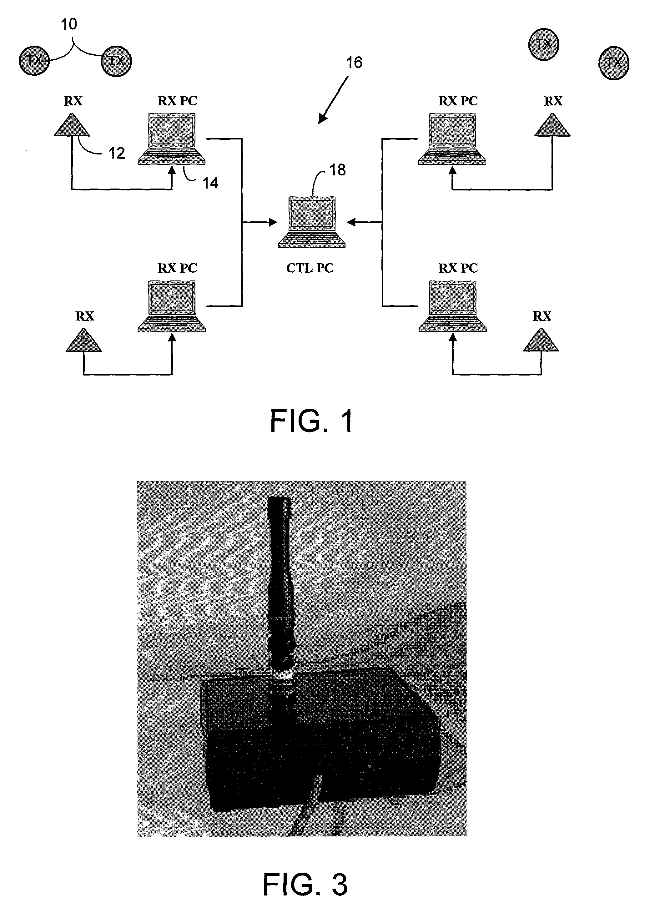
[0037]Referring to FIG. 1, the location tracking system employing the present location measurement process tracks the location of persons and objects carrying radio frequency (RF) transmitters 10 that transmit messages to at least one RF receiver 12. Each receiver 12 is connected to a computing device 14, such as a personal computer (PC) that is in turn part of an existing network 16 of such computing devices. The receivers 12 forward data received from the transmitters 10, along with radio signal strength indicator (RSSI) data, to a centralized computer 18 via the networ...


PUM


Abstract

A process for determining the location of entities carrying transmitters (TXs) that transmit TX ID messages to at least one receiver (RX) connected to a computer, in a network of computers. Each RX sends data messages to its associated computer which includes an identifier identifying the TX transmitting the TX ID message, the signal strength of the received TX ID message, and a RX identifier. Each RX computer generates badge hit messages from each data message, and provides them to a centralized computer of the network. The centralized computer generates a badge hit table having a separate entry for each badge hit message, which has fields including the information received in the badge hit message and a hit time indicating the time the entry was added to the table. The badge hit table data is used to determining the location of the TXs, and so the entities.

Description

BACKGROUND[0001]1. Technical Field[0002]The invention is related to location tracking systems, and more particularly to a system and process for determining the location of persons and objects carrying radio frequency (RF) transmitters that transmit data messages to at least one RF receiver connected to a computer in a computer network. The receivers forward data received from the transmitters to the network, along with radio signal strength indicator (RSSI) data, for computation of the location of the person or object carrying each transmitter.[0003]2. Background Art[0004]Knowledge of the location of people and objects is essential to the viability of many current mobile and ubiquitous computing schemes. For example, in a mobile computing environment, a user of a mobile computing device (e.g., notebook computer, handheld PC, palm-size PC, Personal Digital Assistant (PDA) or mobile phone) may wish the device to provide directions to a particular location in a building, such as the n...

Claims


Application Information

Patent Timeline
Patent Type & Authority Patents(United States)
IPC IPC(8): G06F15/16G01S19/03G06K7/00
CPCG06K7/0008G06K7/10079H04L2012/2841H04W64/00
Inventor KRUMM, JOHNSMITH, GREGORYBRUMITT, BARRETT L.HARRIS, STEPHEN C.
Owner MICROSOFT TECH LICENSING LLC
Why Eureka
Try Eureka