Multi-fixture assembly of cutting tools

a technology of cutting tools and fixings, which is applied in the field of cutting tools assembly, can solve the problems of affecting the performance of the blade, affecting the accuracy of the positioning of the blade's cutting edge, and the blade edge of conventional stainless steel microkeratome blades will typically degrade after use, so as to reduce the potential for movement and enhance the separation of the first blade from the wafer

Inactive Publication Date: 2006-02-07
MEMX
View PDF35 Cites 21 Cited by
  • Summary
  • Abstract
  • Description
  • Claims
  • Application Information

AI Technical Summary

Benefits of technology

[0011]The wafer utilized in relation to the first aspect may include a first score for at least facilitating the separation of the first blade from the wafer when positioned on the second fixture and as will be discussed in more detail below. The first fixture may support the wafer at a location that is directly under the first score. Another way of characterizing how the first fixture supports the wafer in relation to this first score is that the first fixture may support the wafer such that mounting the first blade handle on the first blade does not result in any net moment or torque about this first score. After the first blade handle has been mounted on the first blade, the wafer may be removed from the first fixture and the first blade may be separated from the wafer at least generally along this first score using the second fixture. Separation of the first blade from the wafer may be enhanced by aligning the first score with a predetermined crystal plane of the wafer.
[0012]The first blade may be disposed on a free end of what may be characterized as a first blade support tab or first cantilever. One end of this first cantilever is fixed or anchored (e.g., stationary relative to an adjoining portion of the wafer), while its opposite end (the noted free end on which the first blade is disposed) is movable at least generally about the fixed end of the first cantilever at the appropriate time (e.g., when separating the first blade from the wafer in the above-noted manner). At least a portion of this first cantilever may be supported by the first fixture while the first blade handle is being mounted on the first blade. This then reduces the potential for a movement of the first blade toward the first fixture while mounting the first blade handle on the first blade. There is preferably no deflection of the free end of the first cantilever toward the first fixture while mounting the first blade handle on the first blade.

Problems solved by technology

There are a number of issues with these types of blades.
Various discontinuities (e.g., burrs) may exist along the blade edge based upon the way in which the blade edge is formed (e.g., mechanical grinding, polishing) and the material from which the blade is formed, as well as because of the vulnerability of the cutting edge after being formed.
Certain deficiencies associated with the blade edge may adversely affect the performance of the blade in cutting the eye flap for a LASIK procedure.
Another is that the blade edge of conventional stainless steel microkeratome blades will typically degrade after cutting a single eye flap.
This in turn will affect the accuracy of the positioning of the blade's cutting edge when installed in the microkeratome.
In fact, the inventors associated with the subject patent application do not have knowledge of any silicon microkeratome blade that is commercially available.

Method used


Image

  • Multi-fixture assembly of cutting tools
  • Multi-fixture assembly of cutting tools
  • Multi-fixture assembly of cutting tools

Examples


Embodiment Construction

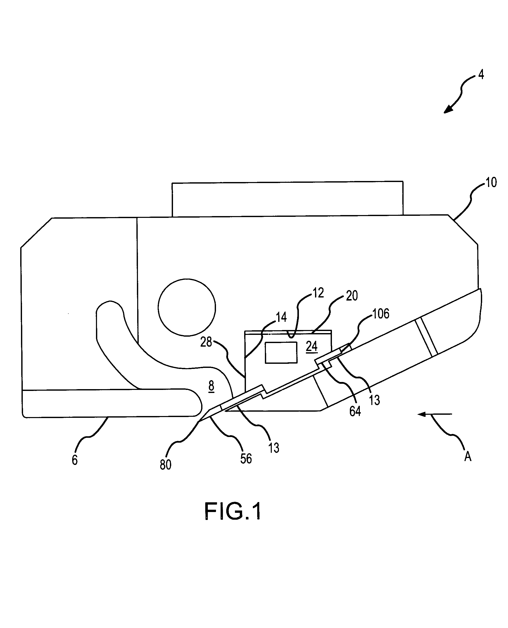
[0062]The present invention will now be described in relation to the accompanying drawings which at least assist in illustrating its various pertinent features. A schematic of one embodiment of a microkeratome 4 that may be used to perform a LASIK procedure on a patient's eye (not shown) is illustrated in FIG. 1. The microkeratome 4 generally includes a head assembly 10 having a presser 6, a cut flap receiver 8, and a cutting tool receiver 12 with a cutting tool 20 disposed therein. Generally, the presser 6 pushes down on the front of the patient's eye while the cutting tool 20 is brought into engagement with and cuts a flap from the patient's eye. Cutting operations generally entail moving the cutting tool 20 in an appropriate manner relative to the patient's eye (e.g., by oscillation of the cutting tool 20 relative to the head assembly 10 in a direction that is parallel with a cutting edge 80 associated with the cutting tool 20 (in and out of the page in the view presented in FIG....


PUM

PropertyMeasurementUnit
thicknessaaaaaaaaaa
blade angleaaaaaaaaaa

Abstract

Multiple cutting blades (56) are fabricated from a wafer (130). This wafer (130) is disposed on a blade handle mounting fixture (224) such that a blade handle (24) maybe mounted on each of the individual blades (56). A cutting edge (80) of each blade (56) is maintained in spaced relation to the fixture (224) as these blade handles (24) are being mounted. Thereafter, the wafer (130) is transferred to a blade separation fixture (300). Each blade 56 is suspended above the fixture (300). An appropriate force is transmitted to the individual blades (56) to separate the same from the wafer (130). Separation preferably occurs before the blade (56) contacts the fixture (300). Thereafter, the blade (56) in effect pivots into an inclined position where its cutting edge (80) projects at least generally upwardly. Preferably, at no time does the cutting edge (80) of any blade (56) contact either the blade handle mounting fixture (224) or the blade separation fixture (300).

Description

FIELD OF THE INVENTION[0001]The present invention generally relates to assembling cutting tools having a separately formed blade handle and cutting blade and, more particularly, to using one fixture to mount the blade handle onto the cutting blade and another fixture to separate the cutting blade from a wafer on which the cutting blade is fabricated.BACKGROUND OF THE INVENTION[0002]Many types of blades exist for many types of applications. Blades are used for cutting biological materials of various types and for various applications. One application that is becoming quite prevalent is the cutting of human eye tissue in relation to a LASIK eye procedure. Here the blade is used in an automated instrument that is commonly referred to as a microkeratome or the like. The blade is used to cut a thin protective layer of corneal tissue from the patient's eye. Typically the cut is made such that this tissue remains attached to the patient's eye, and thus it is commonly referred to as a “flap...

Claims


Application Information

Patent Timeline
Patent Type & Authority Patents(United States)
IPC IPC(8): B23P25/00A61B17/32A61F9/013B26B9/00
CPCA61F9/013A61F9/0133B26B9/00B26B29/06A61B17/3211Y10T29/49885Y10T29/49895Y10T29/49904Y10T29/49996Y10T29/49995
Inventor SMITH, NORMAN FRANKMILLER, SAMUEL LEERODGERS, MURRAY STEVEN
Owner MEMX
Why Eureka
Try Eureka