Fluid coupling for mobile equipment

a technology of mobile equipment and fluid coupling, which is applied in the direction of fluid couplings, clutches, couplings, etc., can solve the problems of speed to droop, and achieve the effects of reducing the number of couplings, and improving the indicator of load

Inactive Publication Date: 2006-02-07
TURBO RES
View PDF8 Cites 1 Cited by
  • Summary
  • Abstract
  • Description
  • Claims
  • Application Information

AI Technical Summary

Benefits of technology

[0027]In the variable speed method of the present invention for controlling the feed stock conveyor, the feed stock conveyor can at times be driven substantially faster than the present common fixed conveyor speed, because most of the time the mill is under-loaded, so that speeding up the conveyor when it is under-loaded and the slip speed is below the set point slip speed will send up more feed stock into the hammer mill in a given period of time. Then when the hammer mill is heavily loaded so that the actual slip speed, for example, 3.7%, is larger than the set point slip speed, say 2.5%, then the controller slows down the conveyor. Control programs using PID (proportional, integral and differential) are readily available and are well known by control designers today. Another reason for using slip speed is that the engine speed is variable and can be set anywhere in the range of 1800 to 2300 rpm, for example, depending upon several variables, including the type of material available, its condition, and the size of the chip desired to be made. In any case, modulating the rate of feed into the mill in order to maintain a given slip ratio will optimize the tons milled per hour and the tons milled per gallon of diesel fuel used, and will keep engine load in normal operating range for a greater portion of the operating time, thereby minimizing air pollution due to abnormal fuel / air ratios.
[0028]Input and output shafts of the fluid coupling are oriented substantially horizontally. A removable reservoir, located vertically below the level of impeller and runner casings and input and output shafts, contains a circulating oil pump within the reservoir, positioned with an intake submerged in circulating oil, so as to be self priming. The circulating oil includes both circuit oil, which fills impeller and runner cavities, and lubricating oil for the bearings. A heat exchanger for the circulating oil is provided with a vent line at its top communicating with the oil reservoir to ensure that the heat exchanger does not become air locked. A temperature control valve is provided to mix cooled oil from the heat exchanger with hot oil that bypasses the heat exchanger to provide oil at a preset temperature to the fluid coupling. A filter is provided to assure that no significant particulate matter enters the bearings. A heating element is provided in the oil reservoir to warm the oil prior to starting the fluid coupling and the diesel in cold weather conditions. An electrically actuated control valve is provided as an oil flow diverter valve that directs circuit oil into the fluid coupling element when the signal to engage the coupling is given, and an over-temperature sensor is provided such that when the temperature of the circuit oil leaving the element exceeds a preset set point value, as occurs when the mill jams, the sensor sends a signal to the controller and on to the diverter valve to divert the circuit oil to the reservoir, thereby permitting the impeller and runner cavity to evacuate, which separates the engine from the load, and the engine can then be brought to idle and cooled down and shut down in a normal manner without damage to any part of the entire power train, and in so doing permit the entire train to be brought back into service after the mill is cleared. The operation of the diverter valve does not affect the operation of the bearing oil lubrication system, which continues as long as the impeller casing is rotating.

Problems solved by technology

Then, an overload of feed stock is what causes the engine to go into overload condition and the speed to droop, but the overload has already occurred and could not be detected until after the fact.

Method used


Image

  • Fluid coupling for mobile equipment
  • Fluid coupling for mobile equipment
  • Fluid coupling for mobile equipment

Examples


Embodiment Construction

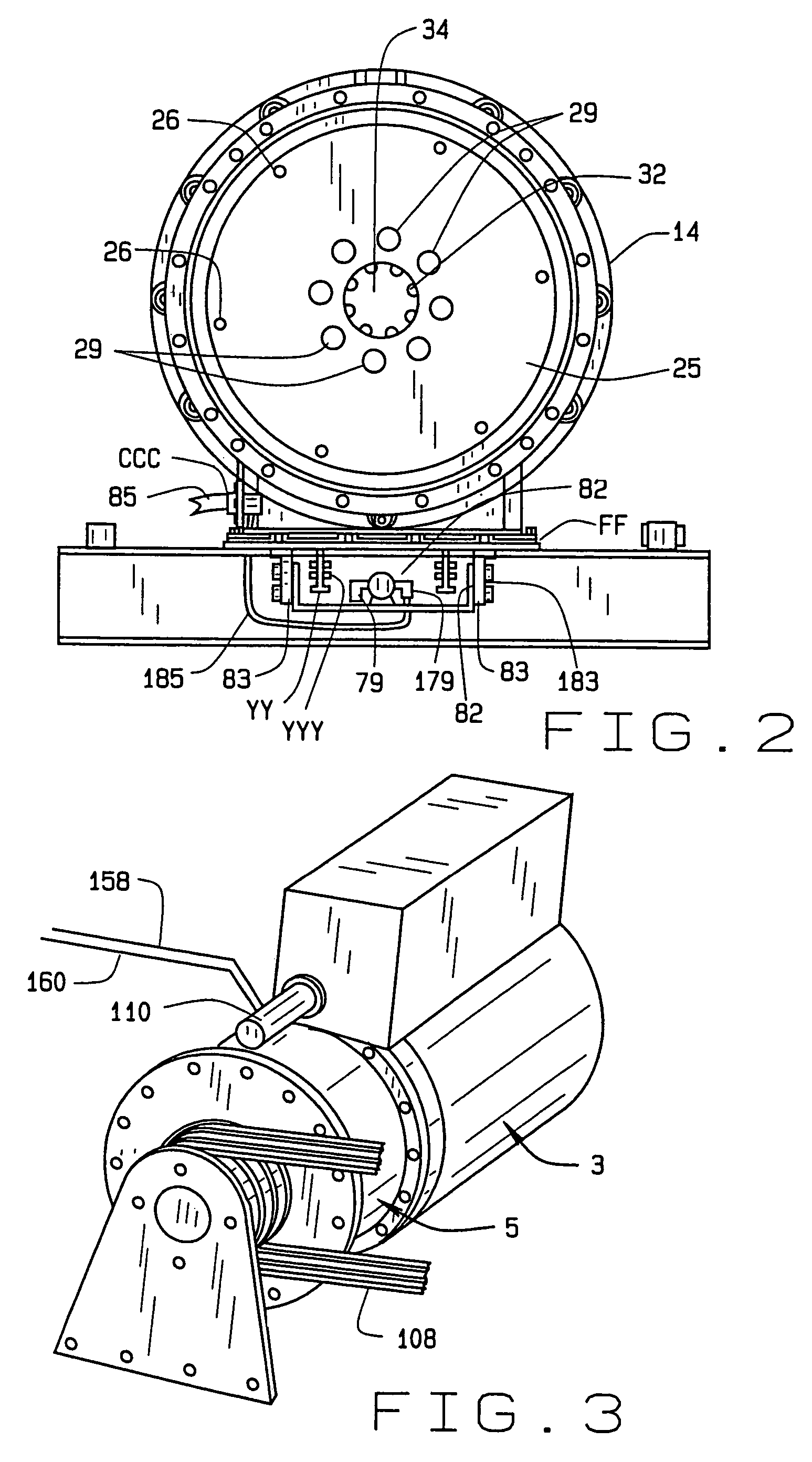
[0042]Referring now to the drawings, particularly FIGS. 3, 4, and 7, reference numeral 1 indicates an entire assembly, including a diesel engine 3 with a hydraulic pump 110 with hydraulic lines 158 and 160 with a hydraulic oil reservoir RR, a fluid coupling 5, a conveyor 9 with hydraulic motor109 with hydraulic lines 163 and 164, accompanying hydraulic controls 10 driven through a communication channel DD by programmable electronic controls 11 with electronic input signal lines 150, 152, and 162, and a hammer mill 12 with driving belts 108.

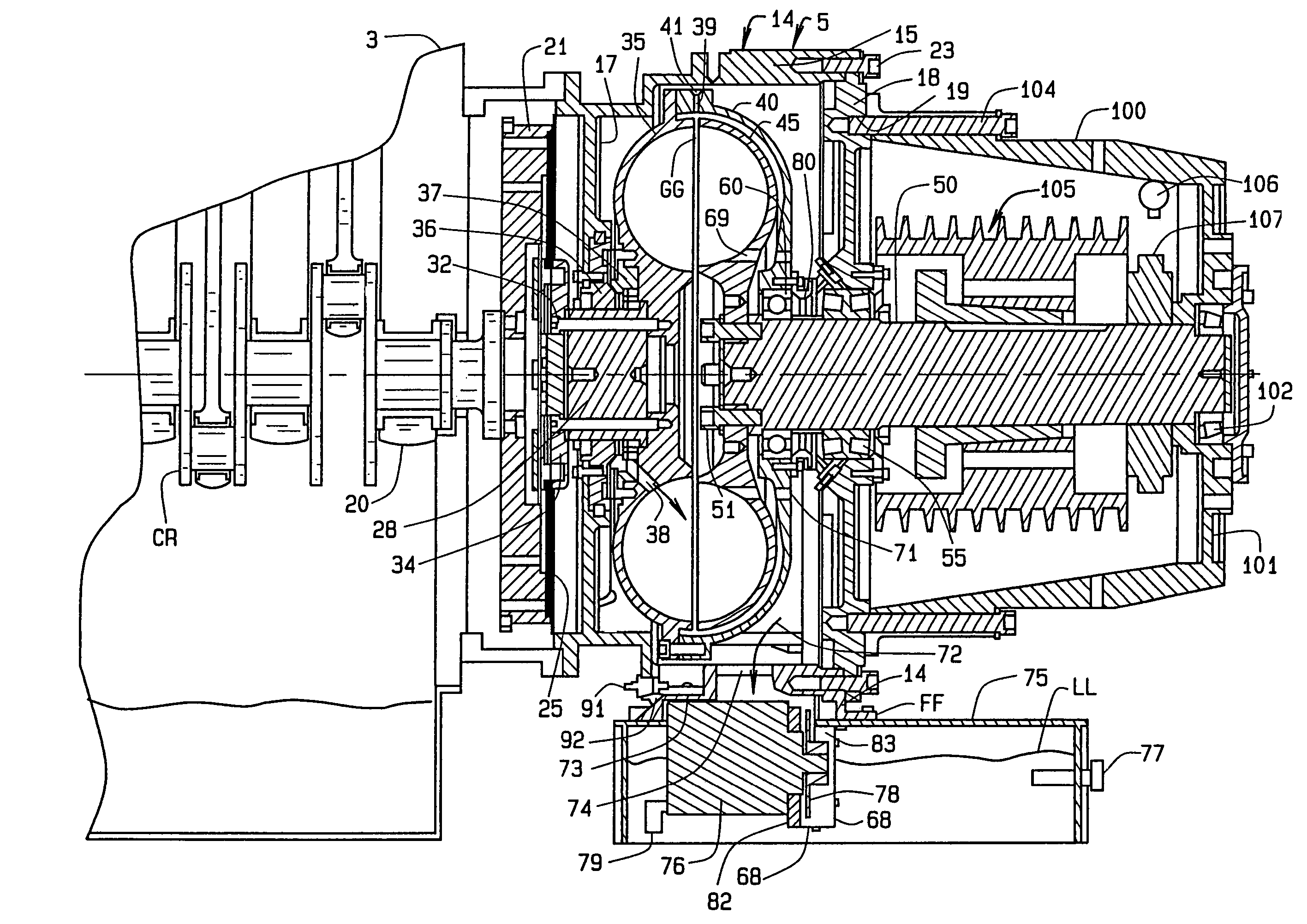
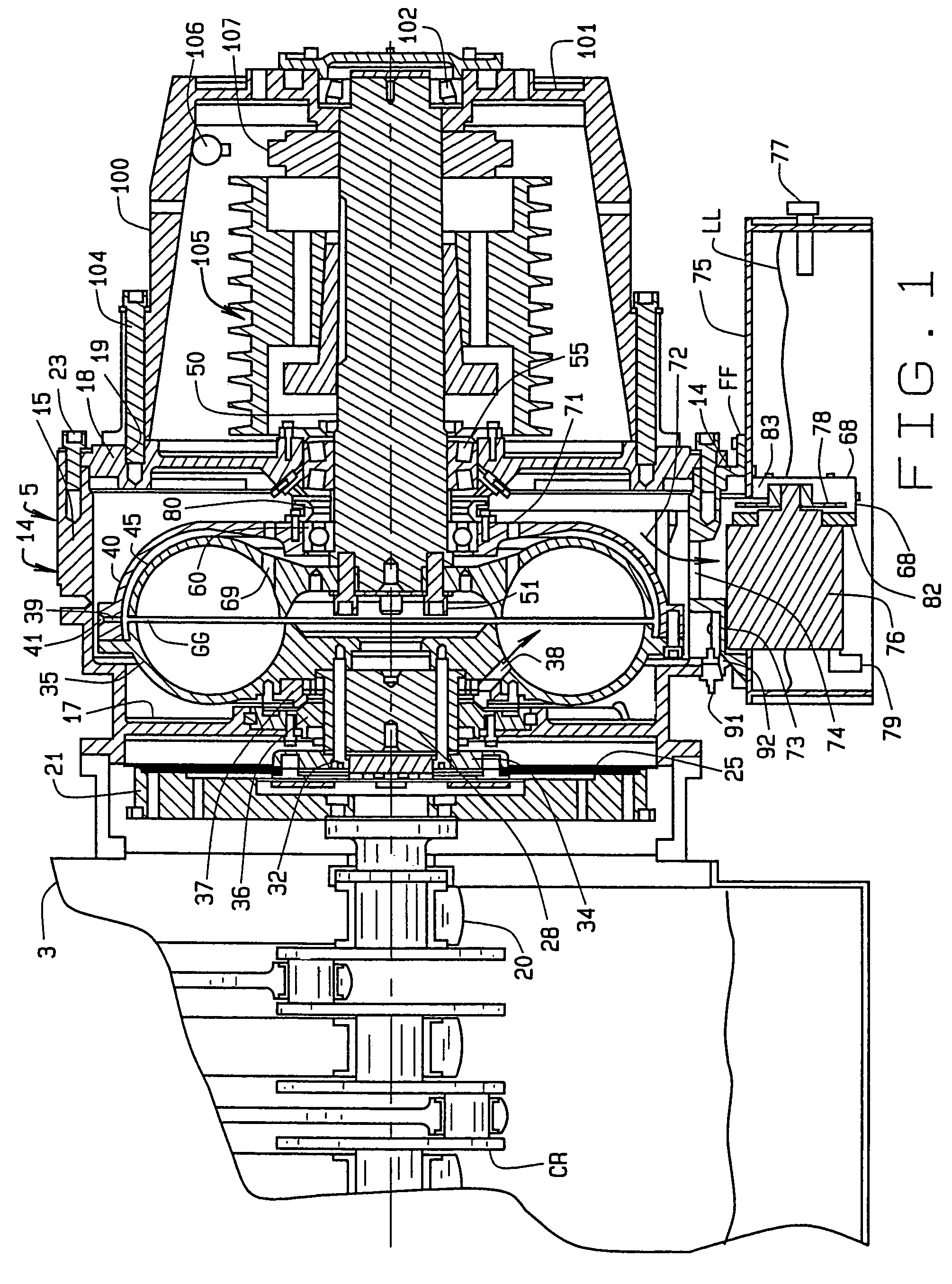
[0043]As is shown in FIG. 1, the fluid coupling 5 has a housing 14, with a generally cylindrical outer wall 15 and a flanged area FF at its bottom to which a reservoir 75 is mounted. At an impeller end of the housing, is an inner wall 17. At a runner end, a heavy wall or center housing plate 18 is bolted to the housing outer wall 15. The plate 18 has a circle of interiorly threaded bolt-receiving bosses 19 opening outwardly.

[0044]The diesel engine...


PUM


Abstract

In an assembly including a diesel engine, a fluid coupling connected to the flywheel of the diesel engine, a comminuting machine and a conveyor for feeding the comminuting machine, a fluid coupling module is common to various output power train assemblies. Slip speed of the fluid coupling between impeller input and runner output shafts is measured, and modulates or regulates the process feed rate of the conveyer. An electrically actuated control valve acts as an oil flow diverter valve directing oil into the fluid coupling impeller when a signal to engage the coupling is given, and in response to a signal from an over-temperature sensor when the temperature of circuit oil leaving the element exceeds a preset set point value, diverts the oil to a reservoir, thereby permitting the impeller and runner cavity to evacuate, which separates the engine from the load.

Description

CROSS REFERENCE TO RELATED APPLICATION[0001]This is a division of application Ser. No. 10 / 171,125 entitled Fluid Coupling for Mobile Equipment, which was filed on Jun. 13, 2002 now U.S. Pat. No. 6,769,248 and which is incorporated herein by reference.STATEMENT REGARDING FEDERALLY SPONSORED RESEARCH OR DEVELOPMENT[0002]Not Applicable.BACKGROUND OF THE INVENTION[0003]This invention has to do with a fluid coupling for use on diesel engine-driven mobile equipment such as wood chippers, rock crushers, road surface grinders (also known as scarifiers or road millers), and the like comminuting mills. This comminuting mill equipment is typically used in conjunction with feedstock conveyors, or in the case of the road surface grinder, used in conjunction with a method to move the grinder along the road to be ground. For controlling the speed and connecting and disconnecting the mills and engines, there are four types of clutch in common use. Three types can be engaged and disengaged with the ...

Claims


Application Information

Patent Timeline
Patent Type & Authority Patents(United States)
IPC IPC(8): F16D33/00B02C23/02F16D33/16
CPCB02C13/30B02C21/02B02C23/02B02C25/00F16D33/16
Inventor GIBERSON, MELBOURNE F.SIMONELLI, MARK T.WIESINGER, JR., FREDERICK C.ABRAMS, GERALD L.
Owner TURBO RES
Why Eureka
Try Eureka