Apparatus and method for controlling the temperature of an electronic device under test

a technology of electronic devices and apparatus, applied in the direction of domestic cooling apparatus, lighting and heating apparatus, instruments, etc., can solve the problems of increasing the size and power consumption requirements of the testing system, requiring extensive insulation,

Inactive Publication Date: 2006-02-07
DELTA DESIGN
View PDF40 Cites 58 Cited by
  • Summary
  • Abstract
  • Description
  • Claims
  • Application Information

AI Technical Summary

Problems solved by technology

Moreover, the entire “cool side” of the liquid loop will often be below dew point, thus requiring extensive insulation.
The liquid loop also increases the size and power consumption requirements of the testing system.

Method used


Image

  • Apparatus and method for controlling the temperature of an electronic device under test
  • Apparatus and method for controlling the temperature of an electronic device under test
  • Apparatus and method for controlling the temperature of an electronic device under test

Examples


Embodiment Construction

[0031]It is to be understood by one of ordinary skill in the art that the present discussion is a description of exemplary embodiments only and is not intended as limiting the broader aspects of the present invention, which broader aspects are embodied in the exemplary constructions.

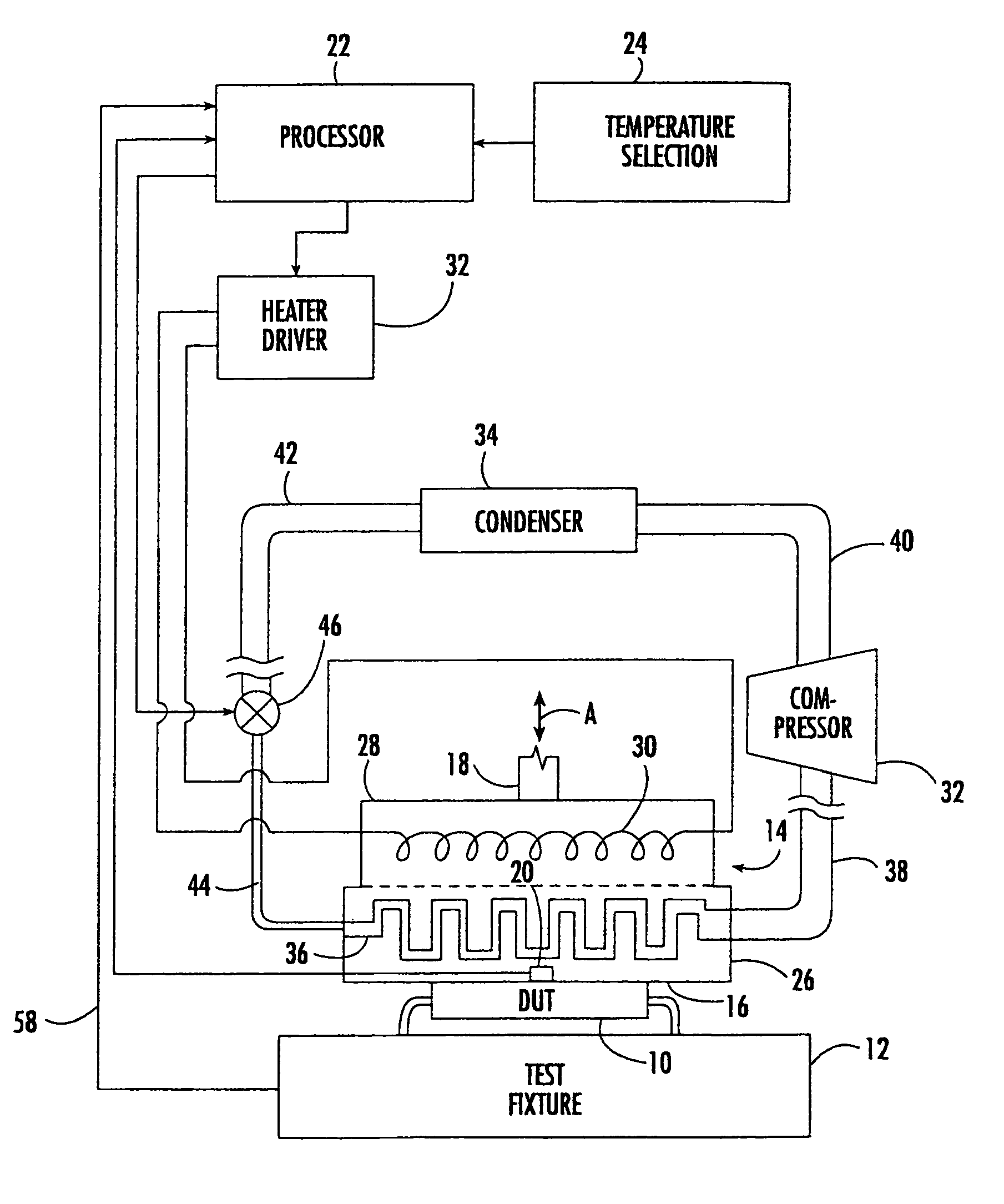
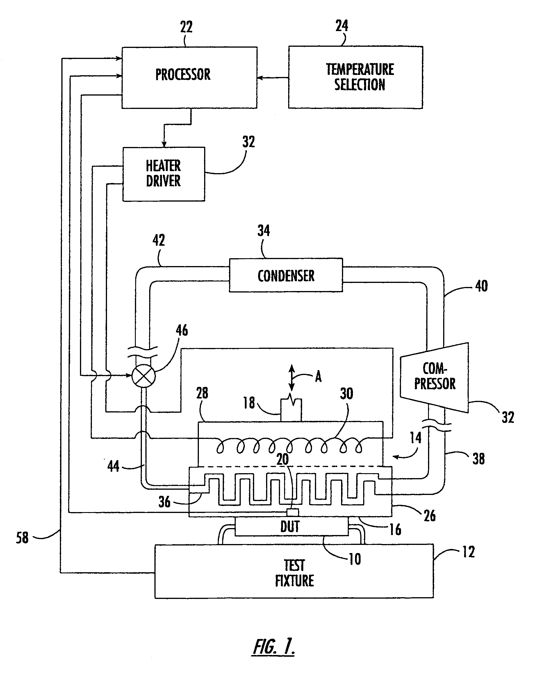
[0032]FIG. 1 illustrates an apparatus for controlling the temperature of an electronic device 10 under test (“DUT”). In this case, device 10 is an integrated circuit device mounted in a suitable test fixture 12. Test fixture 12 supplies the energy to power device 10, as well as the various read / write commands by which the performance of device 10 is evaluated.

[0033]A thermal head 14 has a temperature controlled surface 16 in thermal contact with device 10. In this case, thermal head 14 is attached to the end of a movable rod 18 which operates to move temperature controlled surface 16 into and out of engagement with device 10 (as indicated by arrow A). For example, rod 18 may form the piston rod of a pneu...


PUM


Abstract

An apparatus for controlling the temperature of an electronic device under test includes a thermal head having a temperature controlled surface for making thermal contact with the electronic device. The thermal head defines a flow channel for passage of a refrigerant fluid so as to cause transfer of thermal energy between the electronic device and the thermal head. A refrigeration system is connected in fluid communication with the flow channel of the thermal head to supply refrigerant fluid thereto. The refrigeration system includes a metering valve operative to regulate introduction of the refrigerant fluid into the thermal head. A controller is operative to control the metering valve for maintaining a predetermined temperature at the temperature controlled surface.

Description

CROSS REFERENCE TO RELATED APPLICATION[0001]This application is a continuation of application Ser. No. 09 / 871,526, filed May 31, 2001, now U.S. Pat. No. 6,668,570, which is incorporated herein by reference.BACKGROUND OF THE INVENTION[0002]The present invention generally relates to temperature control systems for maintaining the temperature of an electronic device at a predetermined temperature while the device is being tested.[0003]Testing equipment has been utilized in the electronics industry to test the operation of integrated circuits and other electronic devices maintained at a predetermined temperature. Generally, the testing equipment will include a thermal head having a temperature controlled surface for contacting the electronic device being tested. The thermal head is simultaneously heated and cooled in an attempt to maintain the predetermined temperature. The test equipment users (i.e., electronic device manufacturers) generally specify that the thermal head be capable of...

Claims


Application Information

Patent Timeline
Patent Type & Authority Patents(United States)
IPC IPC(8): F25B41/04G01R31/26B01L7/00F25B1/00F25B41/06F25D17/02G01R31/28G05D23/19
CPCG01R31/2874G05D23/1919B01L7/00F25B41/062F25B2341/062Y02B30/72F25B2600/2513F25B2341/0652Y02B30/70F25B41/347
Inventor WALL, CHARLES B.BARNES, CYNTHIA M.
Owner DELTA DESIGN
Why Eureka
Try Eureka