Apparatus for removing contaminants from crankcase emissions

a technology of crankcase and filter, which is applied in the direction of machine/engine, liquid degasification, separation process, etc., can solve the problems of a large amount of liquid in the fluid stream, and achieve the effects of reducing unwanted engine deposits, improving engine performance, and increasing engine li

Inactive Publication Date: 2006-02-07
NEW CONDENSATOR INC
View PDF25 Cites 23 Cited by
  • Summary
  • Abstract
  • Description
  • Claims
  • Application Information

AI Technical Summary

Benefits of technology

[0008]In accordance with the present invention, provided is a separator that separates the liquids from the gasses and / or vapors in a fluid stream produced by the “blow-by” gasses generated in an internal combustion engine. With this separator, a substantial portion of the fluids in the “blow-by” fluid stream is separated and collected. Only the lighter hydrocarbons are directed back into the intake of the engine and reintroduce with the fuel-air mixture. By reducing the liquids that are reintroduced into the induction system of the engine, engine performance is improved. As stated above, much of the liquid in the fluid stream is contaminated crankcase oil which is not designed to be burned during combustion. In addition, reducing the reintroduced liquids reduces unwanted engine deposits and can increase engine life. Further, improved separation allows the fluid flow produced by a diesel engine to be contained and prevented from passing directly into the environment by way of a “blow-by tube.”
[0009]A separator according to the present invention includes a separating deflector having at least one spiral accelerator extending about a spiral axis between a first and a second end. The spiral accelerator increases the velocity of the fluids of the fluid stream and directs these fluids away from the spiral axis toward non-absorbent beads that at least partially surround the accelerator and which allow a portion of the liquid to be directed into a containment area within the separator.
[0010]A separator according to another aspect of the present invention can include a special housing screen also extending at least partially about the spiral axis to create increased separation of the liquids from the gasses in the “blow-by” fluid stream.
[0011]In accordance with yet another aspect of the present invention, the separator can utilize an outer housing large enough to hold the amount of separated liquids produced by the “blow-by” between regularly scheduled oil changes. The separator can also include a drain apparatus designed to allow easy maintenance or draining of the collected fluids.
[0012]In accordance with yet a further aspect of the invention, the separator can include a pressure relief valve to prevent a failure of engine components due to a back pressure in the system. As a result, the pressure relief valve can be set at a nominal pressure designed to open at the first sign of back pressure.

Problems solved by technology

As stated above, much of the liquid in the fluid stream is contaminated crankcase oil which is not designed to be burned during combustion.

Method used


Image

  • Apparatus for removing contaminants from crankcase emissions
  • Apparatus for removing contaminants from crankcase emissions
  • Apparatus for removing contaminants from crankcase emissions

Examples


Embodiment Construction

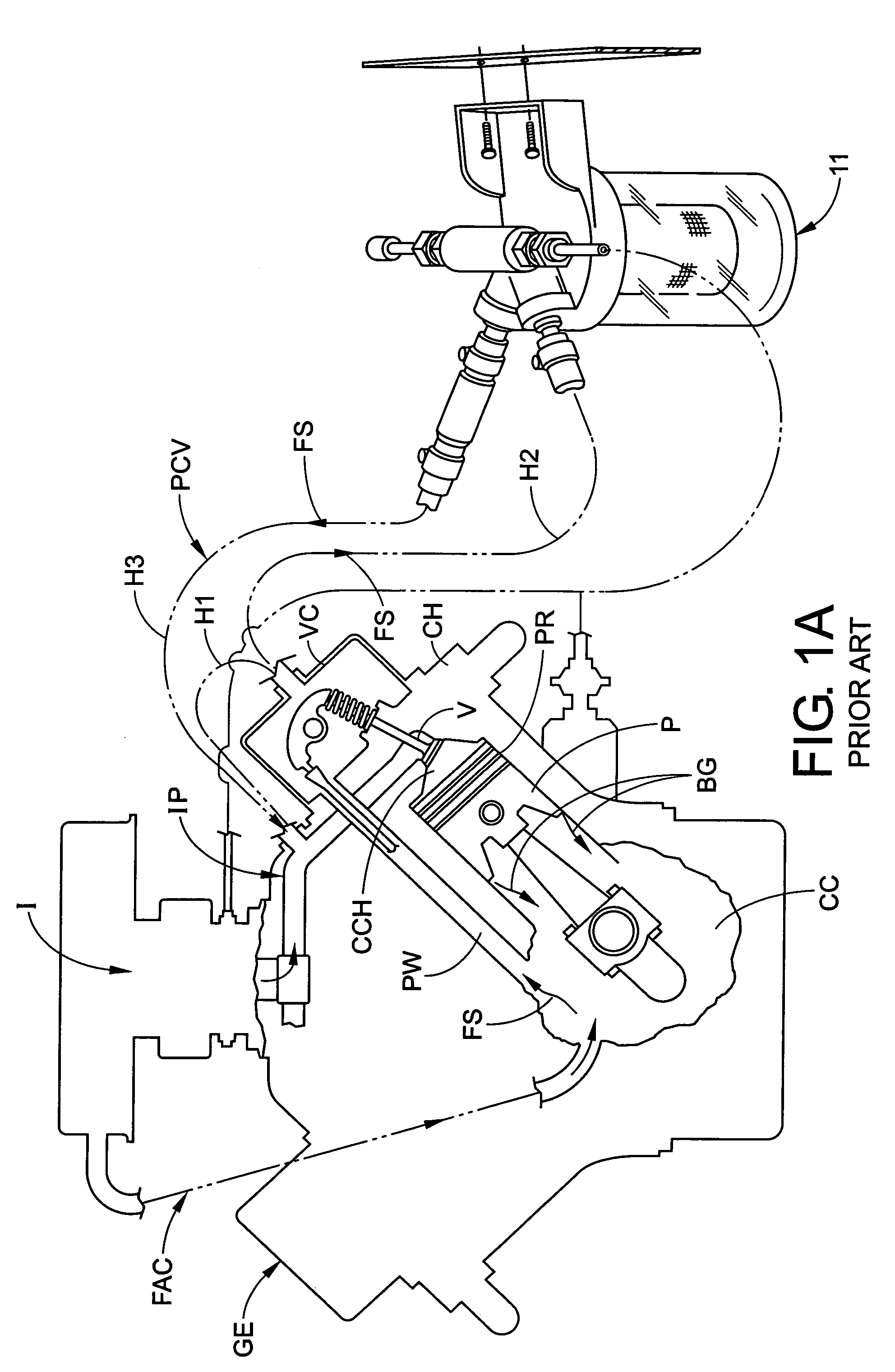
[0030]Referring now in greater detail to the drawings wherein the showings are for the purpose of illustrating preferred embodiments of the invention only, and not for the purpose of limiting the invention, FIG. 1A illustrates a PCV system for a gasolene engine along with a prior art separator used in connection with the PCV system. More particularly, shown is a gasolene type internal combustion engine GE having a crankcase CC, an intake I and at least one cylinder head CH. In operation, intake I delivers a mixture of fuel and air through intake passageway IP into cylinder head CH which is directed to combustion chamber CCH. A valve V regulates the flow of the fuel-air mixture to the combustion chamber. Piston P then compresses the fuel-air mixture wherein during the compression process, a small portion, depending on the condition of the engine, passes by piston P as “blow-by” gasses BG into crankcase CC. In similar fashion, during the combustion of the fuel-air mixture, a portion o...


PUM

PropertyMeasurementUnit
adsorptionaaaaaaaaaa
speedaaaaaaaaaa
pressureaaaaaaaaaa

Abstract

A separator for separating liquids in a fluid stream generated by blow-by gases produced in a crankcase of an internal combustion engine wherein the fluid stream includes both gasses and liquids. The separator including an inlet in fluid connection with the engine for receiving the fluid stream and an outlet in fluid connection with the engine to return a gas stream to the engine. The separator further including a fluid path fluidly connecting the inlet to the outlet and a containment vessel in fluid connection with the fluid path. The separator having a fluid stream accelerator in the fluid path and the accelerator accelerating the fluid stream to at least partially separate the gasses from the liquids in the fluid stream. A deflector, which is also in the fluid path between the accelerator and the outlet, changes the direction of the liquid to direct at least part of the liquids in the fluid stream into a containment portion of the vessel and directs the gas stream to the outlet.

Description

[0001]This application claims priority of provisional patent application Ser. No. 60 / 539,654, filed Jan. 28, 2004.[0002]The present invention relates to a device for removing contaminants from the crankcase emissions produced by an internal combustion engine while in operation and while at idle. More particularly, to a separator for separating the liquids from the vapors in a fluid stream passing from the crankcase of an internal combustion engine. By separating the liquids from the vapors, the vapors can be returned to the intake of the engine to be reintroduced with the fuel-air mixture allowing the vapors to be combusted and causing better combustion while the liquids can be collected for proper disposal. As a result, essentially all of the fluid stream passing from the crankcase is prevented from escaping into the environment.INCORPORATION BY REFERENCE[0003]The present invention relates to separating the liquids from the vapors in a fluid stream generated by an internal combusti...

Claims


Application Information

Patent Timeline
Patent Type & Authority Patents(United States)
IPC IPC(8): F02B25/06B01D19/00F01M13/04F02M25/06
CPCF02M25/06F01M13/04B01D19/0042Y02T10/121F01M2013/0433F01M2013/0427Y02T10/12
Inventor ROBERTS, RICHARD D.BROCK, JAMES R.LOUGHRAN, EDMUND
Owner NEW CONDENSATOR INC
Why Eureka
Try Eureka