Turbine blade and gas turbine

a turbine blade and gas turbine technology, applied in the field of turbine blades and gas turbines, can solve the problems of increasing the temperature of the turbine inlet, generating many respects, and slow casing heat expansion, and achieve the effect of simple maintenan

Inactive Publication Date: 2006-02-07
MITSUBISHI HITACHIPOWER SYST LTD
View PDF9 Cites 56 Cited by
  • Summary
  • Abstract
  • Description
  • Claims
  • Application Information

AI Technical Summary

Benefits of technology

[0045]Therefore, since the holes provided at the top portion of the turbine blade are not covered even if burrs are generated by tip rubbing, the cooling medium for cooling the turbine blade is blown out from the holes. Then, by adopting a turbine blade which includes an outside surface and a top portion to be cooled, the heat resistance prop

Problems solved by technology

However, since the heat resistance performance of each of the members which are exposed to the combustion gas, such as moving blades, stationary blades, and turbine blades, is limited by the physical characteristics of the materials used in the members, the temperature of the inlet of the turbine cannot be simply increased.
However, since the casing does not make direct contact with high temperature gas, the casing undergoes heat expansion more slowly than these moving and stationary blades.
However, if such a relatively large concaving formed by tip squealers 54a and 54b is provided at the top portion TP of moving blade 51 which has a high temperature, disadvantages are ge

Method used


Image

  • Turbine blade and gas turbine
  • Turbine blade and gas turbine
  • Turbine blade and gas turbine

Examples


Embodiment Construction

[0056]An embodiment according to the present invention is explained with reference to the figures.

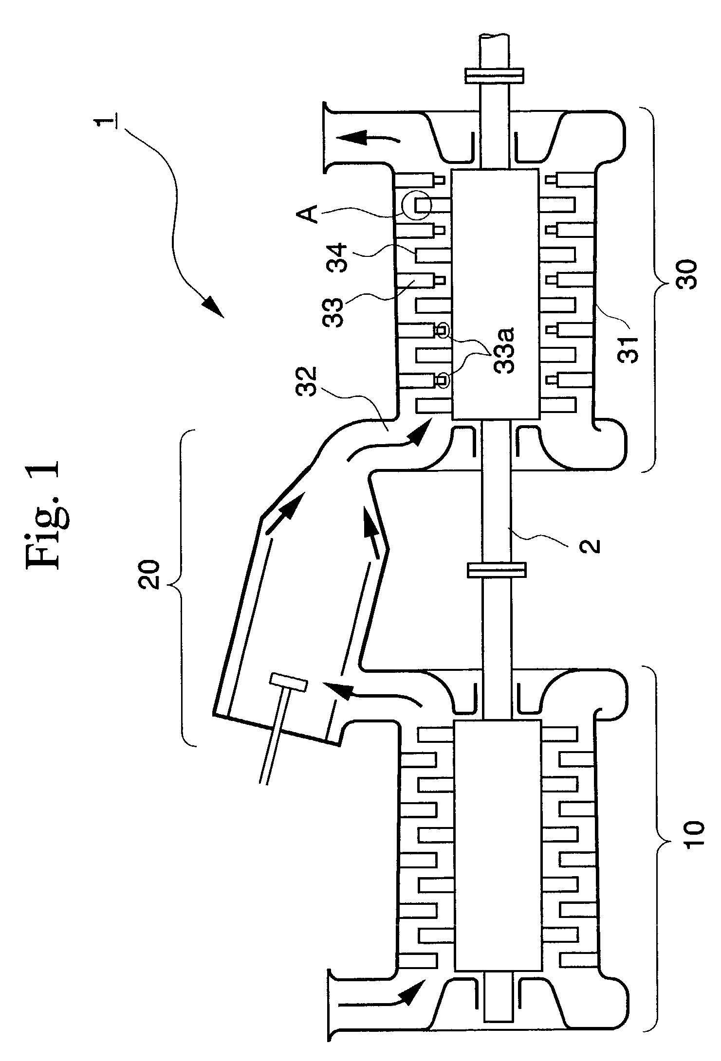
[0057]FIG. 1 is a cross-sectional view explaining a schematic structure of gas turbine 1 according to the embodiment. FIG. 1 shows compressor 10, combustor 20, and turbine 30. Compressor 10 is connected to turbine 30 by rotational shaft 2, and combustor 20 is provided between compressor 10 and turbine 30.

[0058]Compressor 10 compresses a large amount of air therein. In gas turbine 1, generally, a part of the power of turbine 30 obtained by rotational shaft 2 is used as power for compressor 10 (compressor input).

[0059]Combustor 20 carries out combustion after mixing the compressed air in compressor 10 and fuel to send a combustion gas (fluid) to path 32 which is connected to turbine 30.

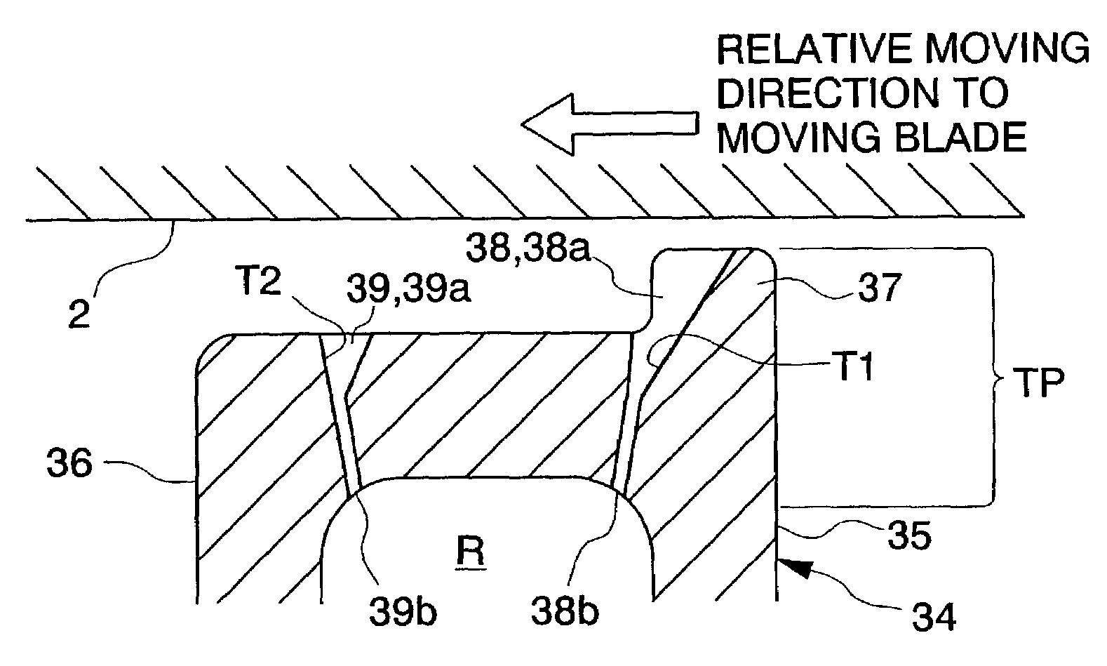
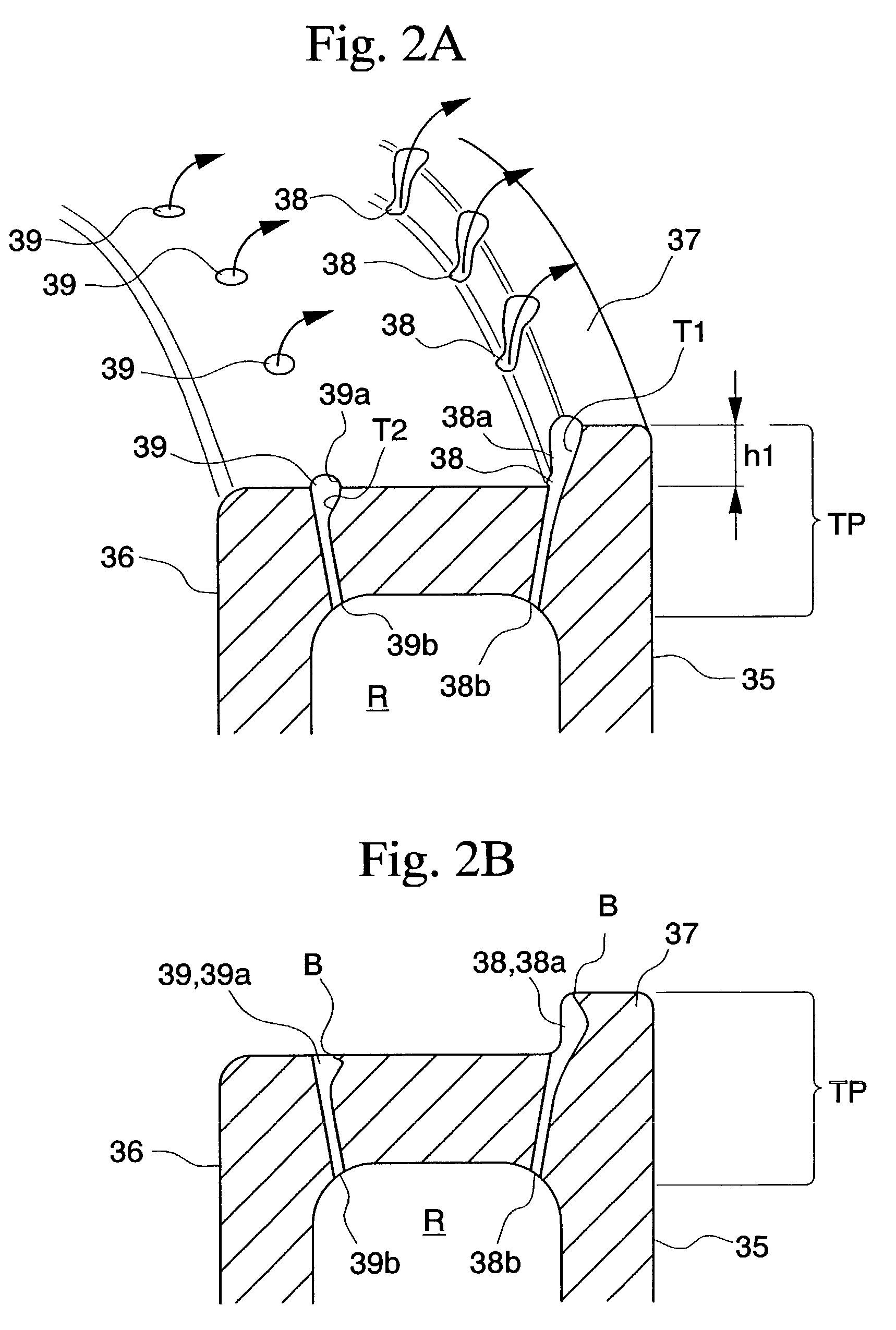
[0060]Turbine 30 is equipped with rotational shaft 2 which extends from, at least, compressor 10 in casing 31 which forms the exterior of gas turbine 1, and plural moving blades 34 and stationary blades 33 ...


PUM


Abstract

Holes 38 and 39 have upstream opening portions 38b and 39b and downstream opening portions 38a and 39a which have a larger cross-sectional area than upstream opening portions 38b and 39b, and are formed at top portion TP of each moving blade. Holes 38 and 39 have tapered shapes T1 and T2 or step portions, and preferably, downstream opening portions 38a and 39a are eccentrically formed toward the moving direction. When tip squealer 37 is formed, hole 38 is formed so that its opening portion is provided at the side surface of tip squealer 37. Without covering the holes for cooling which are formed at the top portion of the turbine blade due to rubbing or the like, the turbine blade is accurately cooled and stably driven.

Description

BACKGROUND OF THE INVENTION[0001]1. Field of the Invention[0002]The present invention relates to a gas turbine which is preferably used for a power plant or the like, and in particular, a turbine blade equipped with a cooling structure.[0003]2. Description of Related Art[0004]To improve heat efficiency of an industrial gas turbine used for a power plant or the like, it is effective that the temperature of a combustion gas (fluid) for operation at an inlet of the turbine is increased. However, since the heat resistance performance of each of the members which are exposed to the combustion gas, such as moving blades, stationary blades, and turbine blades, is limited by the physical characteristics of the materials used in the members, the temperature of the inlet of the turbine cannot be simply increased.[0005]To solve the above problem, since the turbine blades are cooled by a cooling medium such as cooling air or the like, and simultaneously, the temperature of the inlet of the turb...

Claims


Application Information

Patent Timeline
IPC IPC(8): F01D5/18F01D5/20F01D9/02F01D11/04F01D11/12
CPCF01D5/187F01D5/20F01D11/122F05D2260/201F05D2250/292
Inventor SOECHTING, FRIEDRICHTOMITA, YASUOKITORII, SHUNSUKE
Owner MITSUBISHI HITACHIPOWER SYST LTD
Why Eureka
Try Eureka