Electro-mechanical infinitely variable transmission

a transmission and electric motor technology, applied in the direction of electric propulsion mounting, electric gearboxes, transportation and packaging, etc., can solve the problems of system efficiency, engine cannot always operate at the most efficiency speed, and the change of speed ratio is often associated with speed and torque interruptions, so as to eliminate internal power circulation

Inactive Publication Date: 2006-02-07
THE TIMKEN CO
View PDF20 Cites 63 Cited by
  • Summary
  • Abstract
  • Description
  • Claims
  • Application Information

AI Technical Summary

Benefits of technology

[0021]The provision of an electro-mechanical vehicle power transmission which, for the entire designed speed range, from reverse to zero output speed and to hi

Problems solved by technology

Speed ratio changes are often associated with interruptions in both speed and torque.
A major disadvantage of a stepwise vehicle power transmission is system efficiency, since the engine cannot always operate at its most efficiency speed.
For the same reason, pollution is also a problem for a vehicle with a stepwise power transmission.
The hydrostatic traction drives are noisy and have low efficiency, and as such, they generally are used only for low speed applications such as agriculture machines and construction equipment.
Traction drives are more efficient, but they are less rugged for handling large torque loads.
Overall, many tractio

Method used


Image

  • Electro-mechanical infinitely variable transmission
  • Electro-mechanical infinitely variable transmission
  • Electro-mechanical infinitely variable transmission

Examples


Embodiment Construction

[0040]The following detailed description illustrates the invention by way of example and not by way of limitation. The description clearly enables one skilled in the art to make and use the invention, describes several embodiments, adaptations, variations, alternatives, and uses of the invention, including what is presently believed to be the best mode of carrying out the invention.

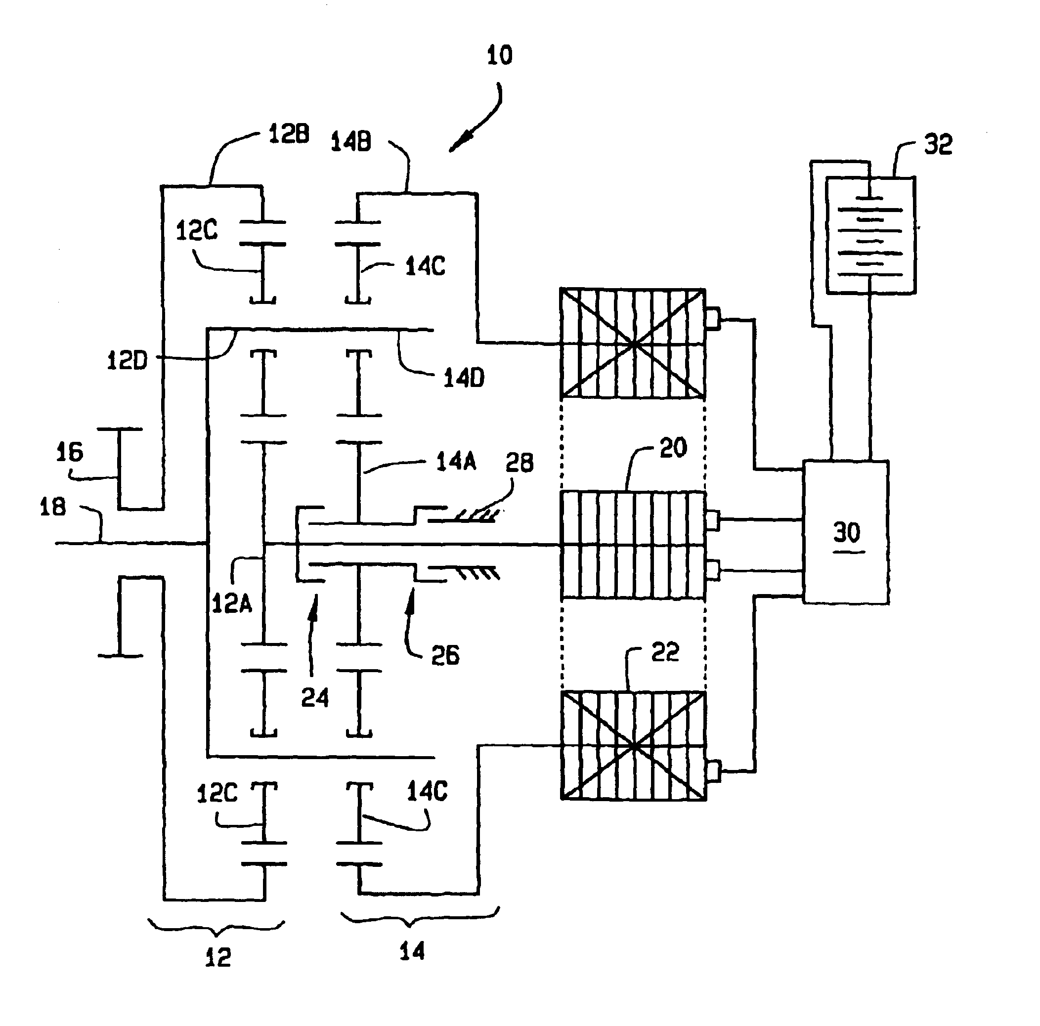
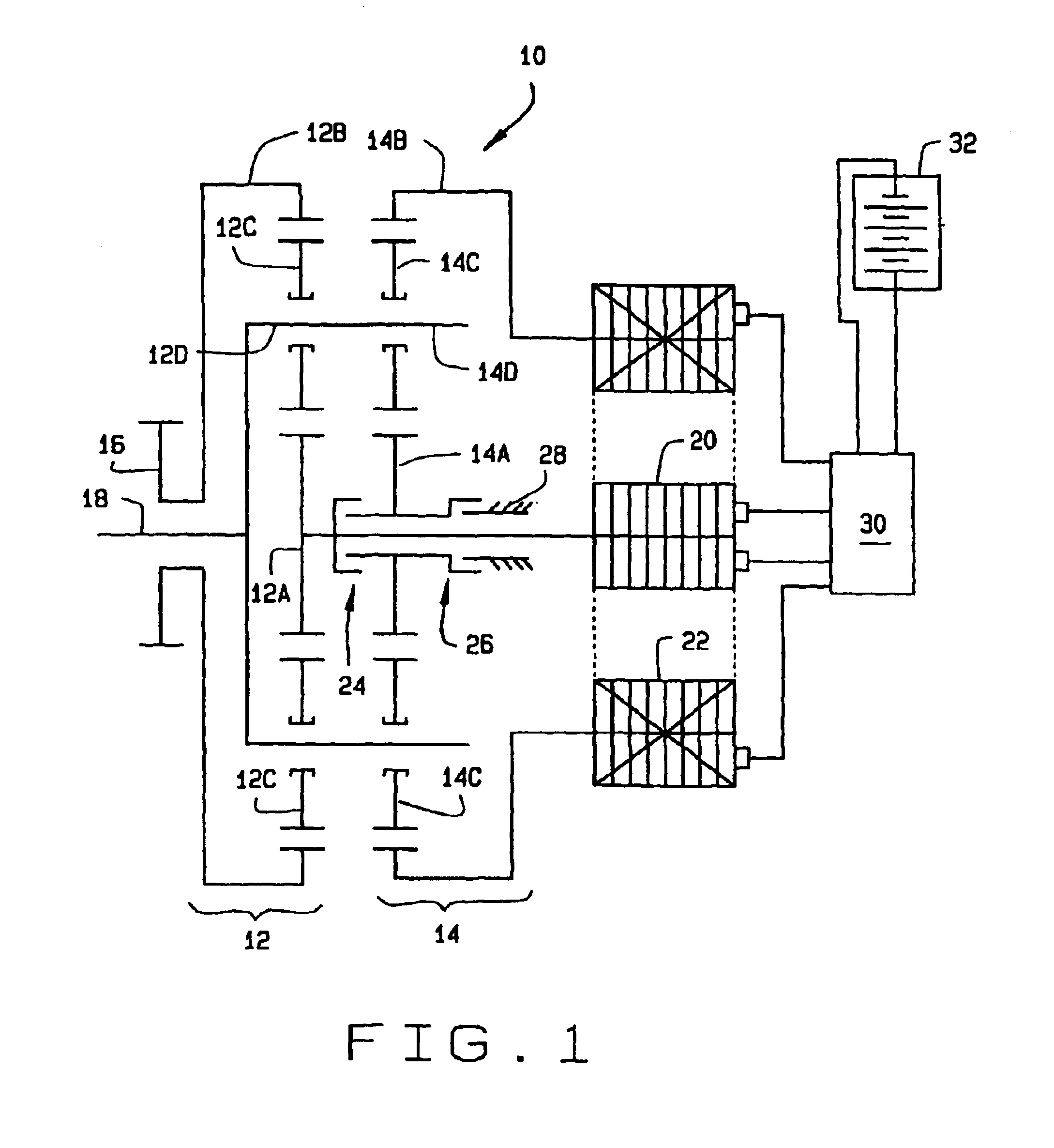
[0041]Referring to FIG. 1, an electro-mechanical hybrid transmission of the present invention is indicated generally at 10. The electro-mechanical hybrid transmission 10 comprises first planetary train, indicated generally at 12, and a second planetary train, indicated generally at 14.

[0042]Each planetary train includes a sun member 12A, 14A, a ring member 12B, 14B, a plurality of planet gears 12C, 14C, and a planet carrier 12D, 14D. The ratio of the pitch diameter of the ring member 12B, 14B to the pitch diameter of the sun member 12A, 14A for each planetary train is referred to as the planetary ratio. T...


PUM


Abstract

An electro-mechanical vehicle power transmission (10) comprises two planetary trains (12, 14) defining mechanical pathways, two electric machines (20, 22) defining an electrical pathway, and at least one torque transfer device (24) that can selectively couple between one component and another component or components to transfer torque. Each planetary train includes a sun member (12A, 14A), a ring member (12B, 14B), and a plurality of planet members (12C, 14C) engaged with the ring member and the sun member. Each planetary train includes a planet carrier (12D, 14D) configured to hold the planet members in an annular space between the ring member and the sun members. Each electric machine can be operated either as a motor to covert electrical energy to mechanical energy or as a generator to convert mechanic energy to electric energy. A first external coupler (16) receives mechanical power from a prime mover while a concentrically disposed second external coupler (18) delivers mechanical power to a driven member.

Description

CROSS REFERENCE TO RELATED APPLICATIONS[0001]This application claims priority to U.S. Provisional Application Ser. No. 60 / 343,336 filed on Oct. 22, 2001, herein incorpated by reference.TECHNICAL FIELD[0002]The present invention relates generally to a vehicle power transmission, and in particular, to a vehicle power transmission which blends the features of a series-hybrid transmission configuration, a parallel-hybrid transmission configuration, a pure electric drive transmission, and a pure mechanical drive transmission over the entire speed range of the vehicle, leveraging the benefits of the series-hybrid configuration and pure electric drive transmissions during slow speed operation and the benefits of the parallel-hybrid configuration and pure mechanical drive transmissions during high-speed operation.BACKGROUND ART[0003]A vehicle power transmission is an important part of a vehicle power train. The primary function of a vehicle power transmission is to regulate vehicle speed an...

Claims


Application Information

Patent Timeline
IPC IPC(8): F16H3/72B60K1/02B60K6/365B60K6/445B60W10/08B60W10/10
CPCB60K6/365B60K6/445B60K6/46B60W10/08F16H3/728B60W10/10B60K1/02Y02T10/6239F16H2037/102F16H2037/106Y02T10/6217Y02T10/62
Inventor AI, XIAOLAN
Owner THE TIMKEN CO
Why Eureka
Try Eureka