Image processing apparatus for joining a plurality of images

a technology of image processing and plurality of images, applied in the field of image processing apparatus, can solve the problems of image distortion, rapid increase in the cost of imaging devices, and unnecessary film development process

Inactive Publication Date: 2006-02-07
OLYMPUS CORP
View PDF11 Cites 114 Cited by
  • Summary
  • Abstract
  • Description
  • Claims
  • Application Information

AI Technical Summary

Benefits of technology

[0039]An object of the present invention is to provide an image processing apparatus which can correct images and be joined by a simple operation based on images themselves without knowing coefficients such as distortion of a camera, and an image processing apparatus which can effectively synthesize an image of a wide dynamic range image from only images.

Problems solved by technology

As a result, developing process for films is unnecessary, and erasing and editing can be easily performed.
However, it is generally known that the cost of the imaging device rapidly rises with the increase in the number of pixels.
However, in general when the photographed image is subjected to influence of distortion due to the optical system, the image is distorted.
If the images are joined by the technique of Japanese Patent Application KOKAI Publication No. 6-141246, the composition of the overlapped parts differs between the images, and there occurs a problem object is seen double in the join image.
As a result, there occurs a problem in which the images are not joined well.
Due to this, it is difficult to get the image having high resolution image or a wide viewing angle image and a panorama image by simply using an arbitrary photographing device which the user has.
Due to this, the images cannot be correctly joined to each other though the images are overlapped with each other.
Due to this, when the images are joined by the above-mentioned technique, color is smoothly changed but the entire image seems unnatural one.
However, in many cases, the digital still cameras on the market have the structure in which the exposure can be adjusted but the user cannot know the ratio exactly.

Method used


Image

  • Image processing apparatus for joining a plurality of images
  • Image processing apparatus for joining a plurality of images
  • Image processing apparatus for joining a plurality of images

Examples


first embodiment

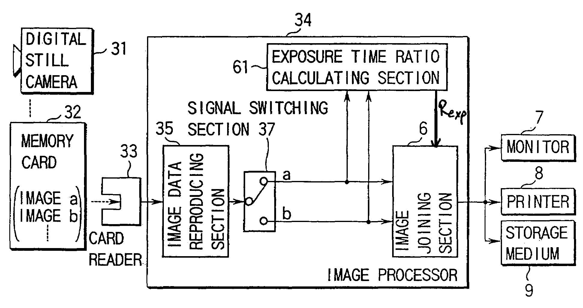
[0085]FIG. 1 shows a schematic structure of an image processing apparatus according to the present invention. This embodiment shows an apparatus for easily correcting distortion as viewing the display or so to synthesize the corrected images, thereby obtaining an image of high resolution and a wide angle image.

[0086]The image processing apparatus of this embodiment comprises a memory card 32, a card reader 33, an image processing section 34, a monitor 7, a printer 8 for a print output, and a storage device 9 such as an optical disk storing images, or a memory card.

[0087]The memory card 32 records image data taken by a digital still camera 31 and a photographing condition data when the image was taken. The card reader 33 reads out image data from the memory card 32. The image processing section 34 reproduces images from those image data, and provides correcting process such as distortion and a white balance to images to be joined. The monitor 7 displays the joined image and original ...

second embodiment

[0109]The following will explain the image processing device of a

[0110]This embodiment, which is a modification of the first embodiment, will be explained with reference to FIGS. 5 to 8. In these figures, the same reference numerals are added to the same structural portions as FIGS. 1 and 2, and the explanation is omitted.

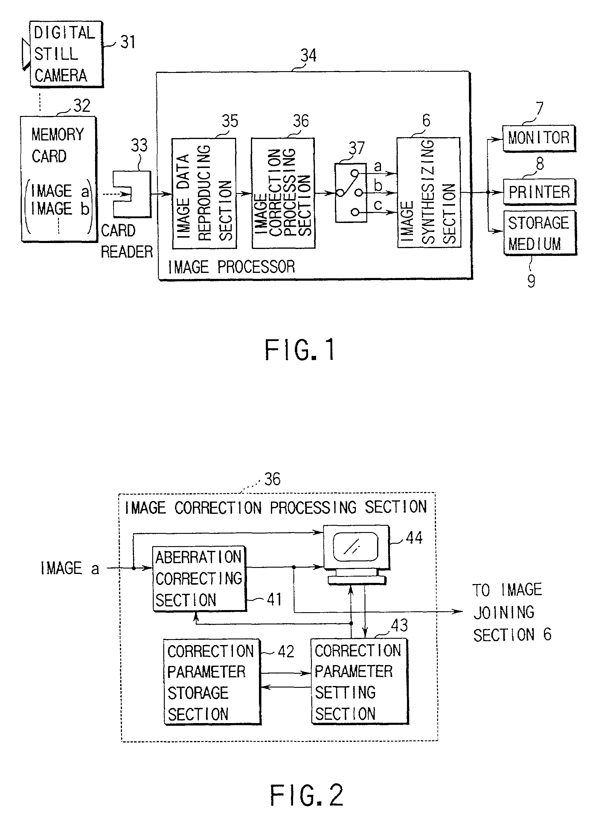
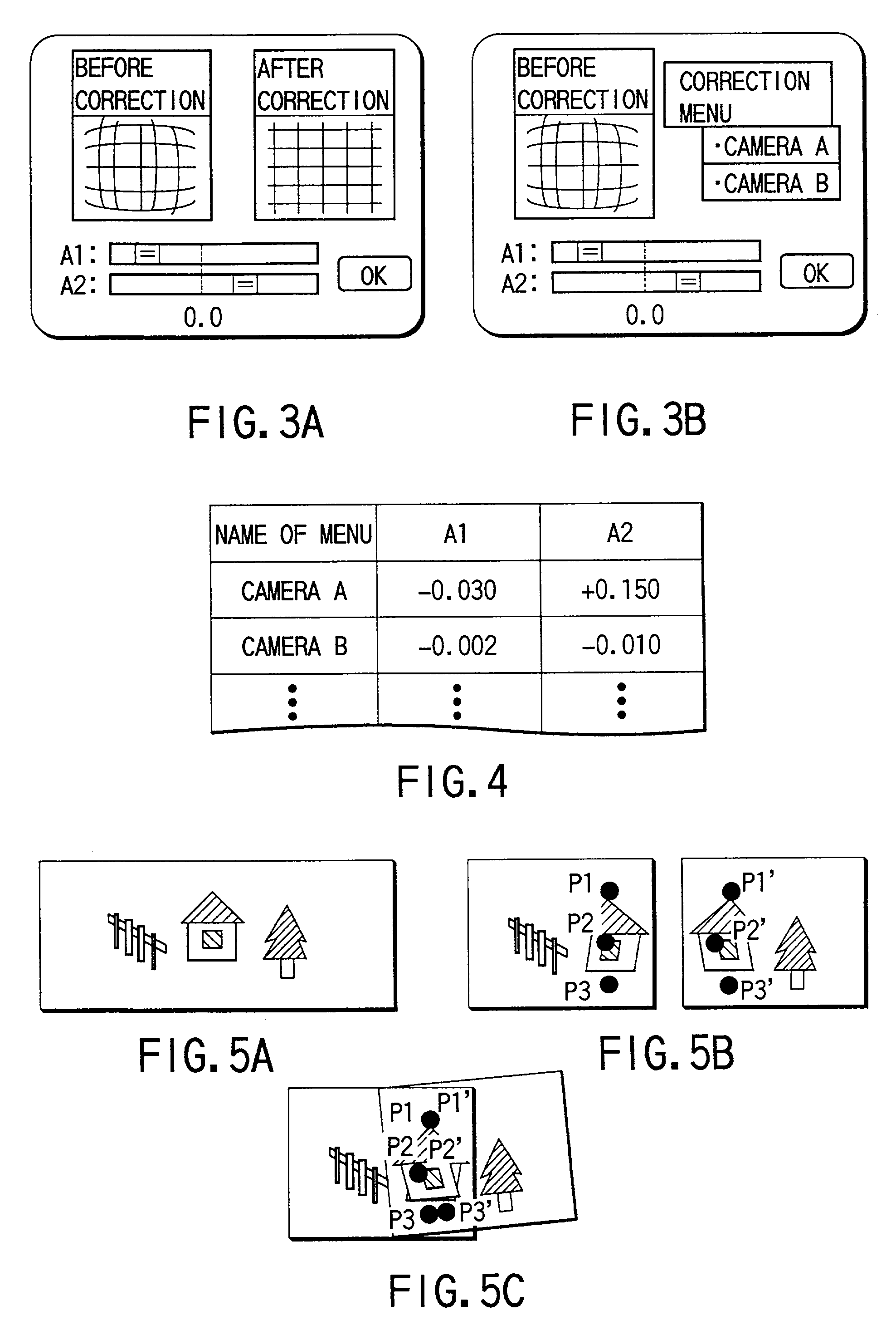
[0111]FIG. 6 is a view showing the structure of this embodiment. The second embodiment is different from the first embodiment in the point that the joined image output from the image joining section 6 is input to the image correction processing section 36. FIG. 7 shows the structure of the image correction processing section 36. FIG. 8 shows one example of the image displayed on the image display section 44 of the image correction processing section 36.

[0112]According to this structure, image data (image a) to which decompression is provided by the image data reproducing section 35 is input to the distortion correction processing section 41 so that data, which is c...

third embodiment

[0120]Next, FIG. 9 shows the structure of the image correction processing section of the image processing device of a

[0121]In these figures, the same reference numerals are added to the same structural portions as the first and second embodiments, and the explanation is omitted.

[0122]Generally, due to influence of peripheral reduction light in the optical system such as a camera, the brightness of the images is reduced as the image advances to the periphery. As a result, when the images with the peripheral reduction light are joined to each other, the image becomes dark at the overlapping area, and an unnatural joining image is generated.

[0123]The peripheral reduction light is a phenomenon in which the brightness of the image becomes darker as a distance R from the center of the image is increased as shown in FIG. 10. A ratio of signal value S′ to an ideal signal value with the peripheral reduction light can be approximately obtained by the following polynomial expression (3):

S′ / S=B...


PUM


Abstract

In an image processing apparatus of the present invention, which displays image data, such as images photographed by imaging apparatus such as a digital camera and photographing conditions as images before correction and images after correction, on an image display section, distortion and color tone of images obtained from an unused camera are corrected and joined to each other as viewing images before and after correction, so that the parameters used in the correction are stored in accordance with its apparatus, and the stored parameters are read out and used to correct in images obtained from previously used camera, and the joined image and image data are displayed on a monitor and output by a printer, or stored in a recording medium.

Description

BACKGROUND OF THE INVENTION[0001]The present invention relates to an image processing apparatus for joining (restoring composition) a plurality of images taken to which one composition is divided with an overlap area where desired object exists or synthesizing a plurality of images taken with a different exposure, and more particularly to an image processing apparatus for extending a viewing angle of a joined image and its dynamic range of a synthesized image.[0002]In recent years, personal computers (hereinafter called PC) got much more capability and their price is reducing in accordance with improvement of manufacture technique, so that they have been widely used in many companies, education, and home.[0003]To input images to PC, an image is optically picked up from a film photographed by a conventional camera and is converted to an image signal to be input.[0004]In addition to camera, imaging apparatus such as a video camera for taking the image are used in various situations. P...

Claims


Application Information

Patent Timeline
Patent Type & Authority Patents(United States)
IPC IPC(8): H04N5/225H04N5/228H04N5/235G06T3/00H04N5/232G06T5/00G06T5/50G06T7/00H04N1/387H04N1/407H04N1/60H04N5/262
CPCG06T3/0081G06T3/4038G06T5/006G06T5/50G06T7/0024H04N1/4072H04N1/60H04N5/23238H04N5/2628H04N1/3876H04N2201/3247G06T7/30H04N23/698
Inventor HIGURASHI, MASAKIKOMIYA, YASUHIROJING, GANGLU
Owner OLYMPUS CORP
Why Eureka
Try Eureka