Methods and apparatus for computer bus error termination

a computer bus and error termination technology, applied in the field of computer bus systems, can solve problems such as complex software, hardware or software faults, and hardware or software faults, and achieve the effect of avoiding the loss of data

Inactive Publication Date: 2006-02-07
STRATUS TECH IRELAND LTD
View PDF213 Cites 34 Cited by
  • Summary
  • Abstract
  • Description
  • Claims
  • Application Information

AI Technical Summary

Benefits of technology

[0005]Accordingly, it is an object of the present invention to provide a process and system for use with a bus architecture within a fault-tolerant computer system to survive bus transaction errors and to allow operations on a bus to continue between the remaining devices after a failure occurs in a device interfaced with the bus.

Problems solved by technology

In any computer system, a fault can occur in a component of the system, either in hardware or software.
A fault can occur due to the intricate nature of the software, which includes complex programming.
Alternatively, the electromechanical devices which make up the hardware upon which the software runs can also fail due to a number of factors such as overheating, power supply problems and the like.
When a failure occurs during a bus transaction, peripherals and other components interfaced with the bus, can become “wedged” or otherwise confused because the bus transaction has been suspended or left incomplete.
This leads to errors in the operation of the bus (“bus faults”), or even failure of the other, non-faulty devices on the bus.
Ultimately, these circumstances can lead to partial or total system failure and can result in costly downtime.
Although this may be tolerable as an inconvenience in some environments, it is clearly not a desirable method for handling such failures in a computer system demanding high-reliability and availability.

Method used


Image

  • Methods and apparatus for computer bus error termination
  • Methods and apparatus for computer bus error termination
  • Methods and apparatus for computer bus error termination

Examples


example

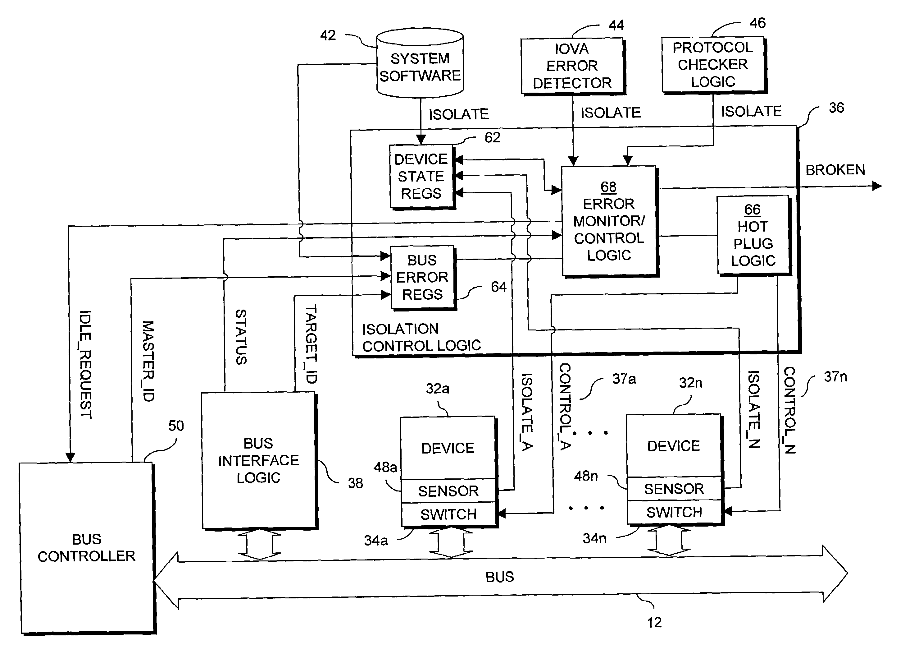
[0042]In an example of one embodiment of the present invention, a device 32 is isolated in response to an error occurring in a PCI bus transaction. Information is communicated between devices 32 connected to a PCI bus 12 through bus transactions consisting, generally, of an address phase and a data phase. A bus-connected device 32 functions as a bus master by requesting access to the bus 12 from the bus controller. After receiving a grant of access to the bus 12, the bus master initiates one or more transactions addressed to one or more target devices 32. A PCI bus includes a number of parallel lines generally grouped into address and data, interface control, error reporting, arbitration and system signal groups. In particular, among other signals, the interface control signals include a cycle frame signal (FRAME#) indicating the beginning and duration of a bus access, an initiator ready signal (IRDY#) indicating the initiating agent's (bus master's) ability to complete the current ...


PUM


Abstract

In a computer system having a bus architecture, a system and process for isolating a device from a bus without interrupting system operation is described, the system including bus interface logic monitoring and reporting activity on the bus, isolation control logic receiving error signals from error detectors, and isolation switches through which devices are interconnected to the bus, the isolation switches allowing for the isolation of the devices from the bus. The isolation control logic determines the devices to be isolated responsive to the reported error and, in turn, transmits an isolation switch control signal to the isolation switch(es) associated with the identified device(s) to isolate those device(s) from the bus. In some embodiments, errors are reported by system software, input/output virtual address error detectors for systems using virtual memory addressing, protocol error detectors, and sensors sensing the physical removal of a bus-connected device from its bus interface slot.

Description

FIELD OF THE INVENTION[0001]The present invention relates to computer bus systems, and more specifically, to methods and apparatus for avoiding bus faults when isolating bus-connected devices from the bus.BACKGROUND OF THE INVENTION[0002]A computer system is a highly-integrated set of components, which may include one or more Computer Processing Units (CPUs), Input / Output (I / O) systems, peripheral components and memory storage devices. Buses are used within the computer system as an interconnect mechanism to carry control messages, data, addresses and other information between components of the computer system. Recent graphics-oriented operating systems, such as Windows NT, include high bandwidth requirements for buses such that the buses need to be capable of moving large amounts of video and other data between computer components.[0003]In any computer system, a fault can occur in a component of the system, either in hardware or software. A fault can occur due to the intricate natu...

Claims


Application Information

Patent Timeline
Patent Type & Authority Patents(United States)
IPC IPC(8): G06F11/00G06F11/07G06F11/30H04L1/22
CPCG06F11/0745G06F11/3055G06F11/3027G06F11/0793
Inventor TETREAULT, MARK
Owner STRATUS TECH IRELAND LTD
Why Eureka
Try Eureka