Method of making a centering device and centering device formed by that method

a technology of centering device and centering device, which is applied in the direction of drilling rods, drilling pipes, other domestic objects, etc., can solve the problems of spring centralisers currently in use, solid centralisers that cannot adequately support tubulars in a central position, and solid centralisers that risk jamming in the borehol

Inactive Publication Date: 2006-02-14
CENTEK
View PDF10 Cites 56 Cited by
  • Summary
  • Abstract
  • Description
  • Claims
  • Application Information

AI Technical Summary

Benefits of technology

[0035]Conveniently the first hinge portion has a first plurality of first finger portions spaced apart in a direction parallel said axis to define a second plurality of openings, wherein said second plurality is one in number less than the second plurality, and the second hinge portion has said second plurality of finger portions for co-operation with a first hinge portion of a further device.

Problems solved by technology

Given the axial variation of diameter of the borehole it is clear that solid centralisers cannot adequately support the tubular in a central position.
Equally being solid, a solid centraliser risks jamming within the borehole.
However spring centralisers currently in use exhibit difficulties with under modern conditions such as depth of well, angular deviation profile and extended horizontal reach into the hydrocarbon producing strata.
As a result they may be made with an oversize outer diameter to create a pre-load effect that gives an acceptable deflection versus load characteristic: however this may create undesirable insertion forces.
This in turn, together with multi-part construction gives rise to the possibility of disintegration.
Known methods of securing together of the parts of the conventional centraliser include welding and mechanical interlocking of the leaf springs to the end bands—both methods of construction detract from the maximum possible load / deflection performance.
. . which are unsatisfactory for construction of centralisers using conventional methods due to such factors as the need for welding the spring bows to the end collars”.
Indeed the disclosure of the U.S. patent is not believed to provide a practical method for manufacturing a centraliser.
Further a device which is manufactured from material to which the method of the Patent can be applied is not believed to have the desired properties of a practical centraliser.
The latter technique would not permit the outward-bowing step as disclosed in the patent.
However, the intermediate bow portions, which are separated by longitudinal apertures, do not confirm to the curved profile of the collar portions due to the presence of the apertures.
Furthermore, unless hot forming is used the tolerances in the bows are unacceptable.
Moreover, as the material used is a spring steel, it is necessary to over-bend the bows and it is not possible to determine consistently how far to over bend the bows to give rise to a desired final form.
This in turn means the use of expensive high temperature form tools with the resultant high tooling attrition.
Apart from the high cost of hot forming in this way, there is the risk of growth of grain within the crystalline structure of the material, which would give rise to weakness and the risk of breakage.
Further, each of the heating steps is likely to give rise to distortion, which reduces the yield and increases the cost.
The technique disclosed in U.S. Pat. No. 3,312,285 makes this form difficult to attain on a consistent basis.
It is therefore believed that the product and method of the U.S. patent is impractical.
If conventional ductile formable materials were used, the method would be capable of putting into effect, but the resultant product would not have the properties required of a centraliser.

Method used


Image

  • Method of making a centering device and centering device formed by that method
  • Method of making a centering device and centering device formed by that method
  • Method of making a centering device and centering device formed by that method

Examples


first embodiment

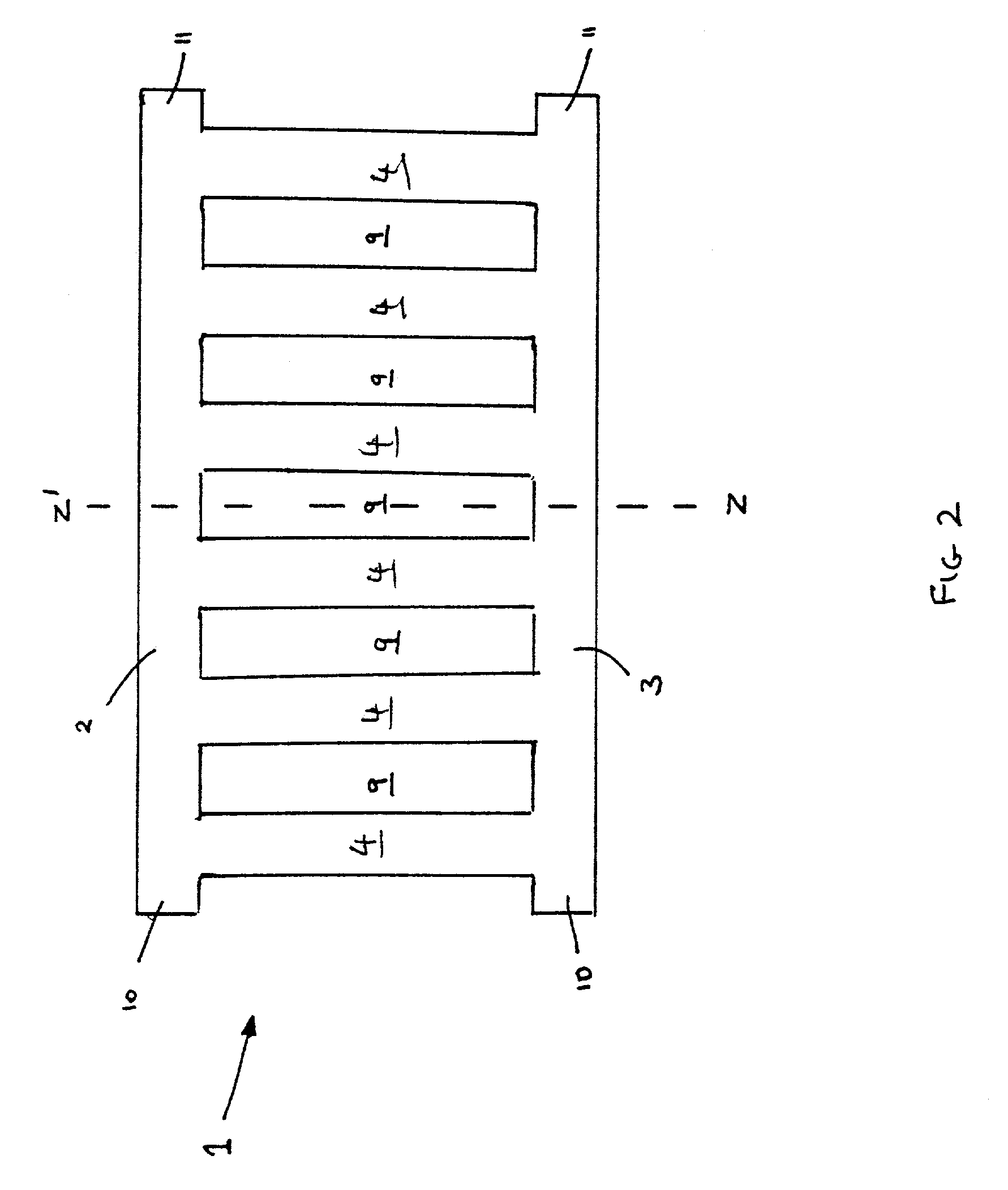
[0092]FIG. 2 shows a blank 1, which has been formed from a single sheet of boron steel. The blank has a longitudinal axis Z–Z′ two transverse web portions 2, 3 spaced apart by a number, here six, of spaced longitudinal web portions 4 which extend substantially parallel (in this embodiment) to the axis Z–Z′. The first and second transverse web portions 2, 3 are generally rectangular in shape, are mutually parallel and are disposed substantially perpendicular to the axis Z–Z′. The six longitudinal web portions 4 extend between the transverse web portions 2,3 to define therebetween five apertures 9 of equal size. The outer longitudinal web portions 4 are inset from the ends of the transverse web portions by around half the width of the apertures 9 to leave free end portions 10,11 of the transverse web portions. The free end portions are, in a centraliser over-lappingly secured together so that each first end portion 10 overlaps its corresponding second end portion 11 whereby the centra...

second embodiment

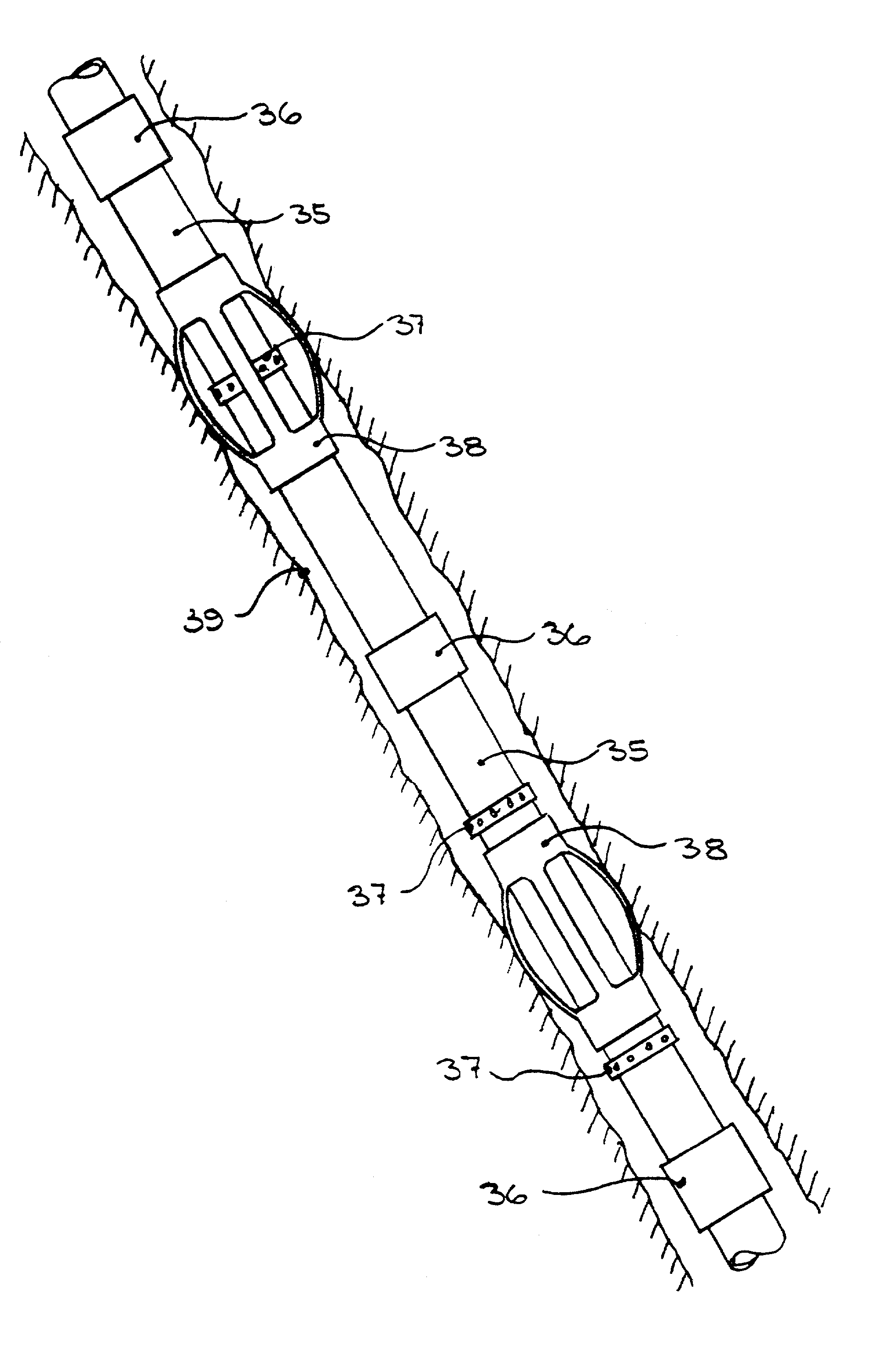
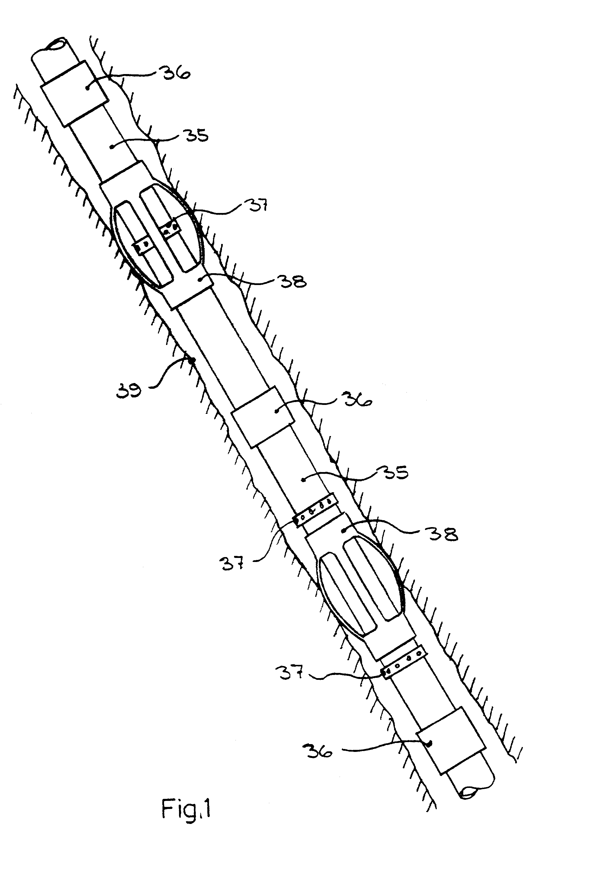
[0115]FIG. 8 shows a centraliser in accordance with the present invention. The centraliser 21 is generally similar to that described with respect of FIG. 3 although it has six bow elements 22, uniformly distributed about its circumference (see FIG. 9). Additionally, however, they are formed at the lower end showed in the Figure of the centraliser, small “tangs”23 extending angularly outwards from the lower collar portion 3. The tangs protrude into the annulus formed between the tubular being centralized and the borehole and have the effect of producing turbulence in fluid passing through the annulus. The tangs are integrally formed with the centraliser. It will be understood by those skilled in the art that tangs may be provided at both ends of the centraliser if desired.

[0116]Referring to FIG. 10, an embodiment of the centraliser blank is shown in which the longitudinal web portions are shaped to have a reduced width where they extend into the end collars 2 and 3. A centraliser of ...

fourth embodiment

[0122]Referring to FIGS. 17 and 18, in the centraliser 40, the form of the bow elements 41 (best seen with reference to FIG. 18) is generally flat.

[0123]Continuing to refer to FIGS. 17 and 18, each bow element 41 has a first substantially straight portion 42 extending downwardly from the first collar portion 2 and laterally away from the longitudinal axis, followed by a second portion 44 which is substantially axis parallel and a third straight line 43 which tapers back to extend into the lower collar at portion 3.

[0124]The fourth embodiment has very rigid properties. Very high loads would be required to deflect the bows and, once the material yield point had been exceeded, there would be virtually no spring recovery. Such rigid centralisers would be made undersize to the borehole, typically six millimeters or more less than the borehole diameter. They might be employed where there was the expectation of high lateral loads of greater magnitude than the restoring force of the central...


PUM

PropertyMeasurementUnit
lengthaaaaaaaaaa
temperatureaaaaaaaaaa
diameteraaaaaaaaaa

Abstract

A spring centralizer device for supporting a tubular member spaced from the wall of a bore is made from a single piece of boron steel material. The spring centralizer device has first and second collars spaced apart along a longitudinal axis. Spring bow portions extend between the collars. As the device is made from a single piece of material, the material extends seamlessly from each collar portion through the bow portions so that there are no joins or points of weakness. Use of boron steel means that the device can be made by cold forming.

Description

FIELD OF THE INVENTION[0001]The present invention relates to a spring centraliser device of the type for maintaining a tubular member spaced from the wall of a bore and to a method of making such a device. Such devices may also be used to space a tubular member within an existing tubular member.BACKGROUND OF THE INVENTION[0002]As known to those skilled in the art, centralisers are used in the oil, gas & water well drilling industries to center a tubular member (hereinafter referred to as a “tubular”) within a borehole or inside a previously installed larger tubular member.[0003]Such tubulars are generally constructed in handleable lengths e.g. 12 meters, each length being externally male threaded at both ends. The lengths are assembled together using short female threaded couplings. The assembly of the tubulars to a predetermined total length is referred to as a string.[0004]When the string is disposed in a borehole or existing tubular, it is desirable to position the string substan...

Claims


Application Information

Patent Timeline
Patent Type & Authority Patents(United States)
IPC IPC(8): E21B17/10B23P15/16
CPCE21B17/1028Y10T29/49609Y10T29/496
Inventor JENNER, ANDREW
Owner CENTEK
Why Eureka
Try Eureka