Clutch having elements capable of independent operation

a technology of independent operation and components, applied in the field of components, can solve the problems of catastrophic clutch failure, limited appeal, and low static torque capacity of non-phased clutches, and achieve the effects of reducing contact fatigue endurance, reducing costs, and reducing the cost of sprag clutches

Inactive Publication Date: 2006-02-14
PEDERSON JACK E +2
View PDF38 Cites 20 Cited by
  • Summary
  • Abstract
  • Description
  • Claims
  • Application Information

AI Technical Summary

Benefits of technology

[0021]Embodiments of the present invention employ possible attributes of each of the three one way clutches described and combine them into one design. A roller clutch, for example, does not require phasing the way a sprag clutch does since it functions with a constant strut angle. Also, a pawl or ratchet clutch does not require phasing. An embodiment of a clutch according to an aspect of the present invention can function without means for phasing, which can serve to reduce costs associated with bearings, cages, or expensive machining operations that generally drive the cost of sprag clutches higher.
[0022]On the other hand, roller clutches cannot handle high relative velocities between the races since centrifugal forces lift the rollers off the inner race, causing the clutch to slip if engagement is attempted. Roller clutches once engaged experience sliding or skidding as the rollers attempt to take up race deflection. This sliding results in reduced contact fatigue endurance over a design

Problems solved by technology

In this regard, non-phased clutches are prone to failure at loads well below their static torque capacity.
Roll over, which is associated with catastrophic clutch failure, occurs, for example, if a first sprag begins to engage prior to other sprags.
Each of the above clutch types, whether formed by a powder metallurgy process or other process, has drawbacks that limit its appeal.
Hoop and contact stresses in a roller or sprag clutch typically require powder having a 7.80 g/cc density, which makes them more expensive than a lower density option.
Further, the number of rollers is constrained because a small roller diameter relative to the cam radi

Method used


Image

  • Clutch having elements capable of independent operation
  • Clutch having elements capable of independent operation
  • Clutch having elements capable of independent operation

Examples


Embodiment Construction

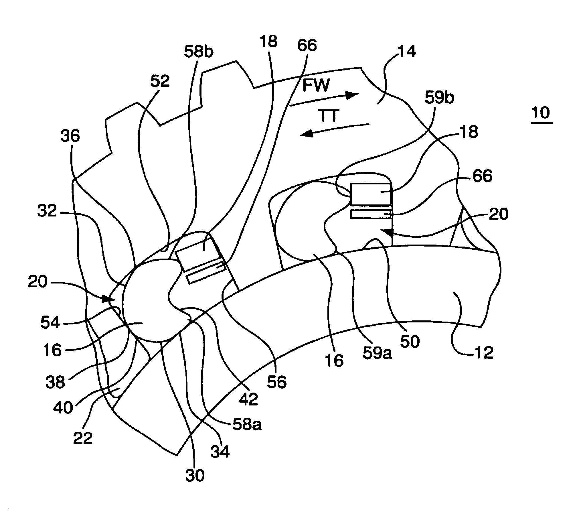
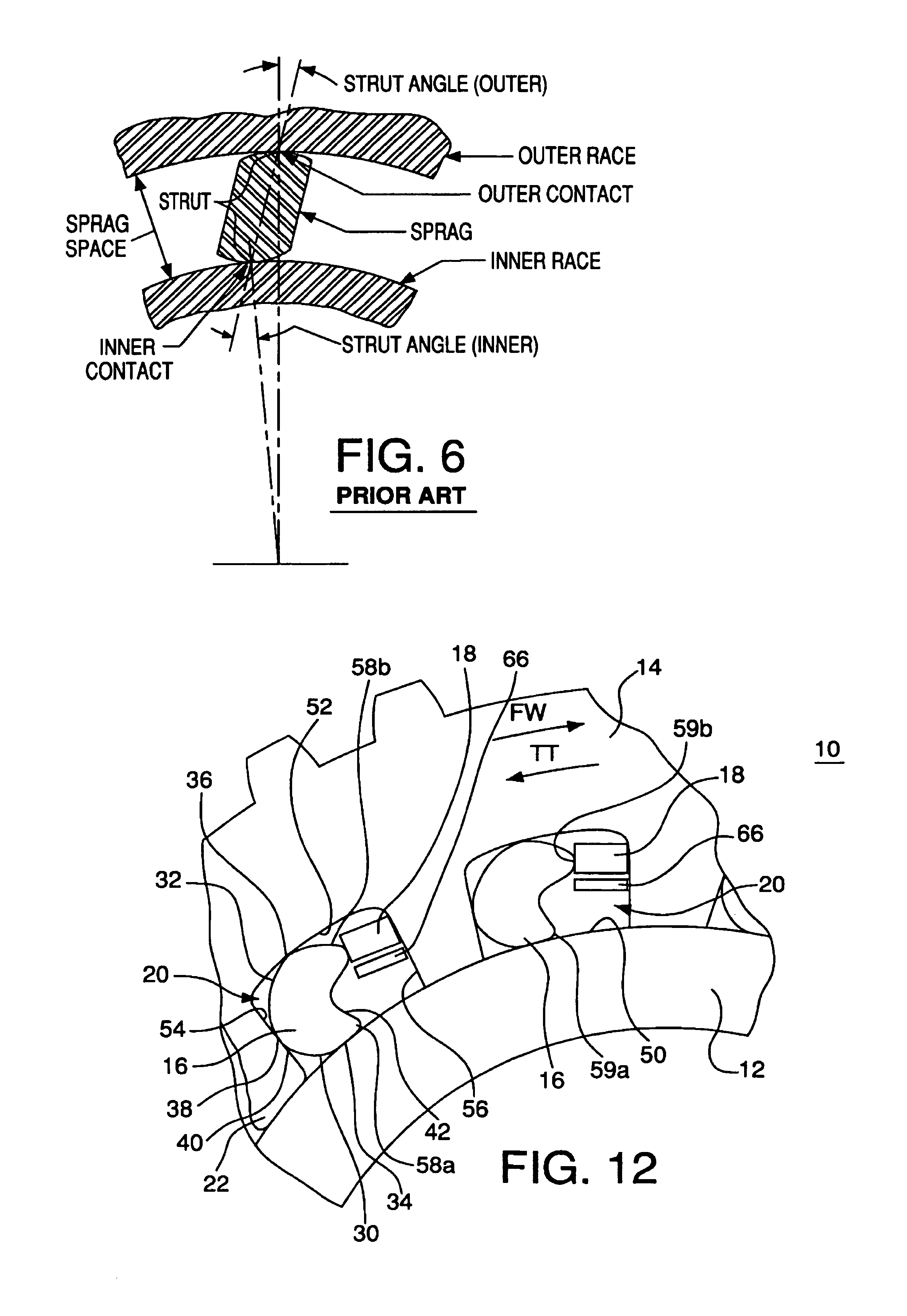
[0057]According to an aspect of the present invention, a clutch 10 includes an inner race 12, an outer race 14, and plural elements 16 disposed between inner race 12 and outer race 14. FIGS. 7A, 7B, and 7C show views of assembled clutch 10. Outer race 14, as best shown in FIGS. 8A and 8B, includes inwardly extending legs 22 that form pockets 20 therebetween. Thus, each pocket is formed by a main outer race surface 52, a pocket rear wall 54, and a pocket front wall 56. Legs 22 may have machined surfaces facing inner race 12 to promote concentricity of races 12 and 14.

[0058]An element 16, as shown for example in FIGS. 9A, 9B, and 9C, and a spring 18, shown in FIG. 10, are disposed in each, or substantially each, pocket 16. Each element 16 includes an inner active surface 30 and an outer active surface 32, which are defined as the portions of elements 16 that contact the inner race 12 and outer race 14, respectively, during normal pivoting of the elements between the freewheeling posit...


PUM


Abstract

A freewheeling clutch includes torque transmitting elements disposed between an inner race and an outer race. The elements include active surfaces that may be defined by an angularly variable radius of curvature that varies with respect to roll angle at an increasing rate, such as an equiangular spiral, to form a constant strut angle as the elements move between a freewheeling and an engaged position.

Description

BACKGROUND[0001]The present invention relates to clutches, and more particularly to overrunning or one-way clutches having elements that are capable of independent operation.[0002]Several types of clutches that transmit torque in one direction are well known. Such clutches typically have torque-transmitting elements—rollers, pawls, or sprags—disposed between an inner race and an outer race. For example, FIG. 1 (Prior Art) shows a roller clutch with pockets, which includes a cam surface, formed in the outer race to contain the rollers. FIG. 2 (Prior Art) shows a roller clutch similar to that shown in FIG. 1, but with a cage that retains the springs and rollers. The springs in the roller clutches shown in FIGS. 1 and 2 bias the rollers toward the narrow end (that is, the portion having the smallest radial spacing) of the pockets. The cam surface of a roller clutch may also be formed on the inner race (although such a configuration is not shown in the figures).[0003]Whether the rollers...

Claims


Application Information

Patent Timeline
IPC IPC(8): F16D43/00F16D41/061F16D41/067F16D41/069
CPCF16D41/069F16D41/067F16D2041/0603F16D2041/0605F16D41/073
Inventor PEDERSON, JACK E.BACON, DUANE A.CHIESA, ALFRED J.
Owner PEDERSON JACK E
Why Eureka
Try Eureka