
Radio frequency data carrier and method and system for reading data stored in the data carrier

a data carrier and radio frequency technology, applied in the field of article identification and authentication, can solve the problems of limiting the use of words in coding the bar code, affecting the accuracy of data processing, so as to achieve the effect of improving the information density

Inactive Publication Date: 2006-02-14
INKSURE RF
View PDF32 Cites 26 Cited by
  • Summary
  • Abstract
  • Description
  • Claims
  • Application Information

AI Technical Summary

Benefits of technology

[0021]Thus, there is a need in the art for, and it would be useful to have, a passive RF data carrier that enables enhanced information density, is free of bulky electronic components, and can be read at no line of sight between the tag and a reading head and over an obstacle.
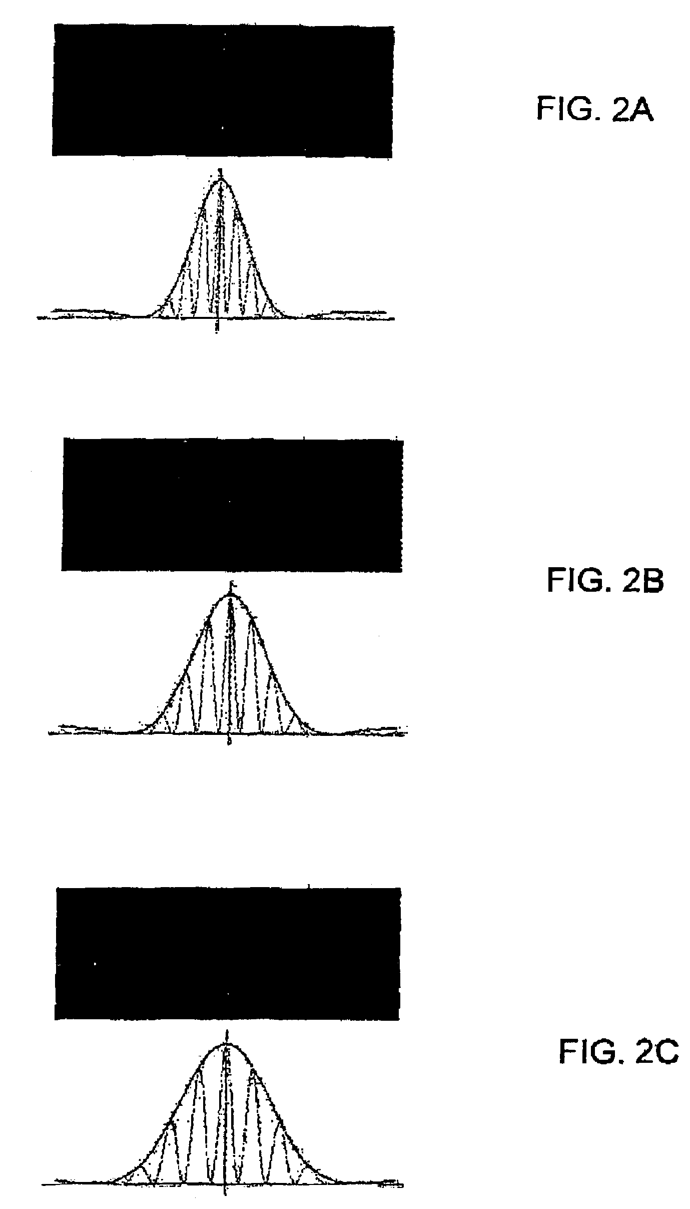
[0025]According to the invention, the diffraction patterns are read and their pictures are recorded, instead of the pictures of objects. Since the patterns have an angular structure, the position of the origin can be traced back even behind an obstacle, minimizing the effect of “collision” between different objects. In other words, the process of reading the data carrier of the present invention is not prevented, even if the carrier is placed beyond the line of sight. This feature provides an opportunity to read several carries at the same time.
[0032]The RF data carrier way include an additional substrate surface carrying at least one additional diffraction element. These two substrate surfaces may be the opposite surfaces of a common substrate layer. In this case, the substrate may be made of a material which is impermeable to the RF radiation of a first predetermined wavelength band used for reading the diffraction element on one surface, while being transparent to a second predetermined wavelength band of the RF spectrum used for reading the diffraction elements on the second surface, or vice versa. Such a data carrier, having several substrate surfaces (or layers) with diffraction elements, can be employed to increase the capacity of the stored data. For example, in a double layer data carrier, information can be recorded by using the diffraction elements in the upper substrate layer using a material, which is reactive to a specific wavelength and transparent to a second wavelength that reacts with the lower substrate layer. Such combinations of additional substrate layers and diffraction elements can form multiple substrate layer data carriers.
[0048]The information-carrying tag (e.g., multi-bit tag) of the present invention has advantageous features. In particular, there is no strict requirement for the data carrier of the invention to be appropriately positioned for radiation and detection. The diffraction elements associated with the data carrier can produce a collection of diffraction patterns having an angular structure under irradiation with RF electromagnetic radiation. Since the pattern has an angular structure, the position of the origin can be traced back even behind an obstacle, minimizing the effect of “collision” between different objects. In other words, the process of reading the data carrier of the present invention is not prevented, even if the carrier is placed beyond the line of sight of the detecting device. This feature provides an opportunity to read several carriers at the same time. The RF radiation utilized for irradiating the data carrier of the invention can readily penetrate into the environment of detection that provides the possibility for the user to read the tag at no line of sight between the tag and reading head. The data carrier of the invention can have the advantage that a viewer can not, without aid, see the hidden data marking that can be concealed under an opaque (or black) layer. This makes forgery difficult. On the other hand, appropriate scanning devices can readily detect the data makings. The multi-bit data carrier according to the present invention may be of rather high information density. The data carrier according to the present invention may be easily and efficiently manufactured and marketed, is of durable and reliable construction, and may have low manufacturing cost.

Problems solved by technology

While inexpensive and effective, the optical bar code system, however, has certain limitations, for example, the “words” utilized in coding the bar code, have a relatively long length due to their binary nature.
Despite the extensive prior art existing in the area of multi-bit information carriers based on barcodes and optical diffraction gratings, there are certain disadvantages associated with the utilization of such devices.
One of the main drawbacks of the techniques based on the use of bar codes and optical diffraction gratings is related to the fact that the bar codes and optical diffraction gratings must be visible, which limits the locations in which they may be placed.
Thus, bar codes and optical diffraction gratings can easily be obscured, either accidentally or intentionally.
Therefore, as soon as a counterfeiter learns the method of duplication, the barcodes and optical diffraction gratings become worthless for authentication purposes.
Moreover, because barcodes and optical diffraction gratings are exposed to ambient medium, the barcodes and optical diffraction gratings are susceptible to damage that can result in detection failures.
Therefore, the barcodes and optical gratings cannot be placed beyond the line of sight of the detecting device.
Last, but not least, the disadvantage is also associated with the fact that multiple items utilizing the barcodes and optical diffraction gratings must be scanned (read) one at a time.
These constraints of bar code systems and optical diffraction gratings make them undesirable or inefficient for some applications.

Method used


Image

  • Radio frequency data carrier and method and system for reading data stored in the data carrier
  • Radio frequency data carrier and method and system for reading data stored in the data carrier
  • Radio frequency data carrier and method and system for reading data stored in the data carrier

Examples


Embodiment Construction

[0058]The principles and operation of the information-carrying multi-bit data carrier and identification system according to the present invention may be better understood with reference to the drawings and the accompanying description, it being understood that these drawings and examples in the description are given for illustrative purposes only and are not meant to be limiting. The same reference numerals will be utilized for identifying those components which are common in the multi-bit data carriers shown in the drawings throughout the present description of the invention.

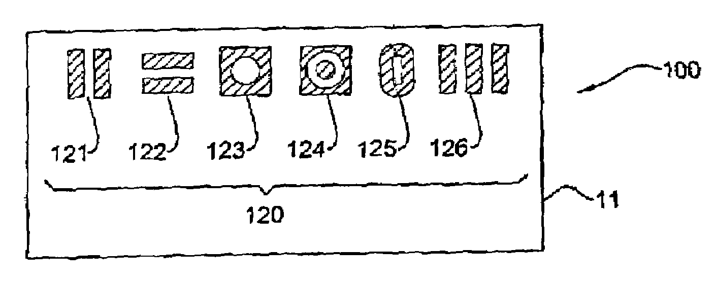
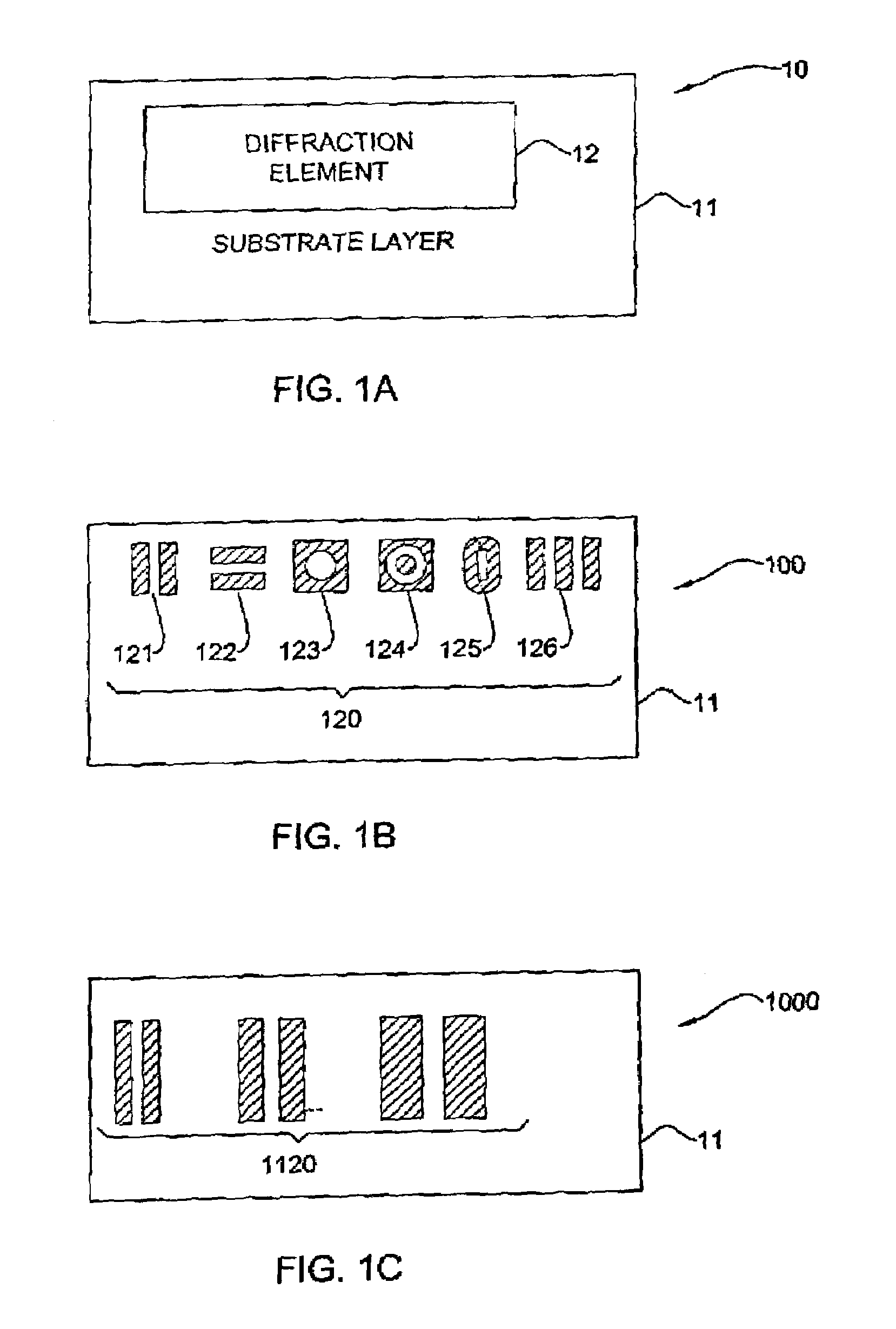
[0059]Referring now to the drawings, FIG. 1A illustrates a data carrier 10 according to one embodiment of the invention. The data carrier 10 comprises a substrate layer 11 whose surface is patterned to have a diffraction element 12. It should be noted that the relative size and position of the diffraction element 12 are shown in FIG. 1 only as a non-limiting example, and are not drawn to scale. The element 12 ...


PUM


Abstract

A radio frequency (RF) data carrier is presented. The RF data carrier comprises at least one diffraction element that has a dimension of the order of a wavelength of RF radiation and is responsive to RF irradiation, the response produced by the diffraction elements in the data carrier being indicative of machine-readable data carried by data carrier.

Description

FIELD OF THE INVENTION[0001]This invention is generally in the field of article-identification and authentication, and relates to an RF data carrier, and a method and system for reading information stored in such a data carrier.BACKGROUND OF THE INVENTION[0002]Electronic Article Surveillance (EAS) systems are widely used to detect the presence of small electronic labels placed on or in an article or carried by a person of interest, and can, for example, be used in retail or library environments to deter theft or any other unauthorized removal of articles. In particular, the EAS labels are attached to articles designated to either be purchased or borrowed, and when active, will trigger an alarm if carried without authorization through interrogation zones typically located at the store or library exits.[0003]There are many applications when it is also desired to know more information than just whether a tagged object is present. For example, very often users also want to know which ta...

Claims


Application Information

Patent Timeline
IPC IPC(8): G06K19/06G06K7/10G06K19/067
CPCG06K7/10009G06K19/067G06K2019/0629
Inventor YOGEV, AMNONDUKLER, SHLOMO
Owner INKSURE RF
Learn More