Method for determining vision defects and for collecting data for correcting vision defects of the eye by interaction of a patient with an examiner and apparatus therefor

a technology applied in the field of eye examination and data collection, can solve the problems of falsification of even or odd-valent aberrations, and achieve the effect of easy capture and good utilization basis

Inactive Publication Date: 2006-02-14
CARL ZEISS MEDITEC AG
View PDF4 Cites 81 Cited by
  • Summary
  • Abstract
  • Description
  • Claims
  • Application Information

AI Technical Summary

Benefits of technology

[0036]In a preferred method of one aspect of the present invention the adaptive data for a subjectively optimal correction condition of the eye are obtained by a subjective assessment of modified test images by the patient, modified by the change of mirror positions of mirrors of the adaptive optics. The change of the mirror position of the individual small mirrors allows one to compensate for any aberration condition of the eye. The position of the individu...

Problems solved by technology

The main problem with this method resides therein that the uneven or odd-valent aberrations are determined in a falsified manner.
This s...

Method used


Image

  • Method for determining vision defects and for collecting data for correcting vision defects of the eye by interaction of a patient with an examiner and apparatus therefor
  • Method for determining vision defects and for collecting data for correcting vision defects of the eye by interaction of a patient with an examiner and apparatus therefor
  • Method for determining vision defects and for collecting data for correcting vision defects of the eye by interaction of a patient with an examiner and apparatus therefor

Examples


Embodiment Construction

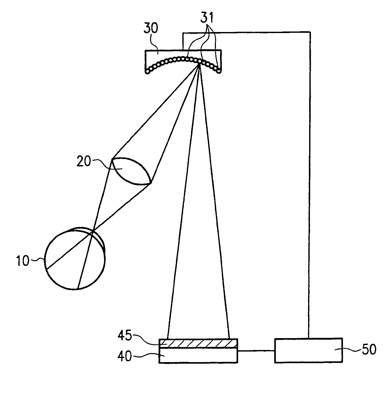
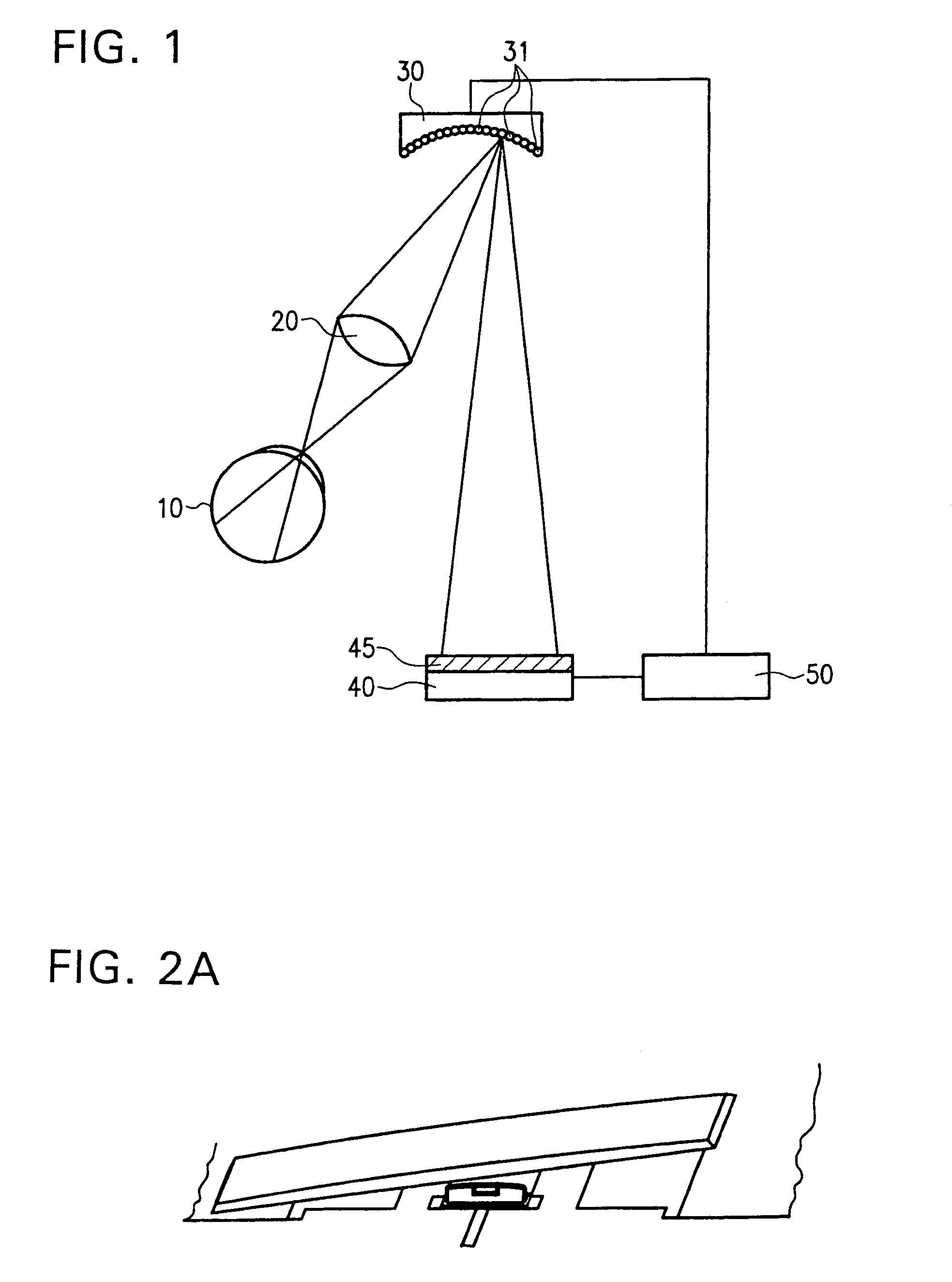
[0055]FIG. 1 is a block circuit diagram of an apparatus embodiment in accordance with one aspect of the invention. The eye 10 considers, via a lense 20, a mirror-field, or an array of mirrors, of an adaptive optics 30 comprised of individual mirrors 31. An arrangement 40 for the projection of test images selectively produces test images45. A control system 50 is connected to the arrangement 40 for the projection of test images and to the adaptive optics 30.

[0056]The test image 45 is produced by way of the arrangement 40 for the projection of test images and is projected onto the adaptive optics 30. The individual mirrors 31 project the test image, via lens 20, onto the retina of the eye 10. The control system 50 captures the attitude of the individual mirrors 31 and the selection of the test image 45.

[0057]The patient now judges the subjective or actual quality of the image of the test image 45 on the retina of the eye 10, preferably by responding with “good” or “bad” in response to...


PUM


Abstract

There is now provided a method for determining vision defects and for collecting data for correcting vision defects of the eye. The method comprises projecting an image into the eye of the patient with an adaptive optical system having adaptive optical elements. The optical characteristics of the optical elements can be individually changed by an electrical signal. The presence of distortions of the image as perceived by the patient is determined by interaction of the patient with the examiner. By way of an electronic control system the optical characteristics of the adaptive optical elements are changed through outputting of an electrical signal to obtain a modified image with minimized distortions in the eye of the patient. The optical characteristics of the adaptive optical elements, as modified, are determined and vision correcting data for the eye being examined are computed from the optical characteristics of the adaptive optical elements, as modified. The method not only takes into consideration the aberrations of the optical imaging system but also the properties of reception and signal processing in the human brain. The method is further characterized in that the correction data for the aberrations of the human eye that impair the vision can be obtained by a measuring method that is actively physiologically evaluated beforehand. There is also provided an apparatus for determining vision defects and for collecting data for correcting vision defects.

Description

CONTINUING APPLICATION DATA[0001]This application is a continuation of application Ser. No. 10 / 160,345, filed May 31, 2002, now U.S. Pat. No. 6,722,767 which is a Continuation-in-Part application of International Application No. PCT / EP00 / 12116, filed on Dec. 1, 2000 and claiming priority from Federal Republic of Germany Patent Application No. DE 199 58 436.2, filed on Dec. 3, 1999. International Application No. PCT / EP00 / 12116 was pending as of the filing date of this application. The United States was an elected state in International Application No. PCT / EP00 / 12116.BACKGROUND OF THE INVENTION[0002]1. Field of the Invention[0003]This invention relates in one aspect to a method for determining vision defects and for collecting data for correcting vision defects of the eye by interaction of a patient with an examiner and apparatus therefor.[0004]2. Background Information[0005]The primary or traditional method for correcting vision defects, such as, correcting myopia, hyperopia, and ast...

Claims


Application Information

Patent Timeline
IPC IPC(8): A61B3/10A61B3/02A61B3/103
CPCA61B3/14A61B3/103A61B3/0025
Inventor DICK, MANFREDMAUSEZAHL, HOLGERSCHRODER, ECKHARD
Owner CARL ZEISS MEDITEC AG
Why Eureka
Try Eureka