Lamp with reflecting mirror and image projecting apparatus

Active Publication Date: 2006-02-14
PANASONIC CORP
View PDF4 Cites 4 Cited by
  • Summary
  • Abstract
  • Description
  • Claims
  • Application Information

AI Technical Summary

Benefits of technology

[0014]It is therefore an object of the present invention to produce a reflecting-mirror-equipped lamp capable of being downsized and fabricated at a lower cost as well as ensuring connection reliability.
[0026]In one embodiment, the caulking member has a cylindrical shape. In one embodiment, each of the pair of external leads is made of molybdenum, and the caulking member is made of a material more plastic than molybdenum constituting the external leads. The caulking member is preferably made of a material having excellent oxidation resistance.

Problems solved by technology

As a result, a discharge might occur at the connection portion 20, so that it is difficult to adopt the wrapping technique.
That is to say, the welding strength at the connection portion 20 is low, so that there is a problem that the welded portion is often separated by handling during assembly.
Furthermore, there found a problem that since the tips of the external lead 1104 and / or the outward-drawn lead wire 1204a are / is exposed to the outside because of the absence of a base as shown in FIG. 1B, the tip serves an antenna to generate a strong noise especially upon the application of a high-pressure pulse at the start of operation.
In particular, a projector using a full digital device such as a DMD is vulnerable especially to noise, so that noise is a serious problem.
In addition, since the tip of the wire is exposed to the outside, injury is likely to occur in replacing a lamp.
However, such a configuration is disadvantageous especially for cooling in a lamp with a small reflecting mirror, resulting in another problem.
In addition, in the case of the lamp with a small reflecting mirror, the temperature at the neck portion 1306 is prone to increase, so that oxidation develops rapidly if the connection is made by welding.
As a result, there arises a problem of a short lifetime.

Method used


Image

  • Lamp with reflecting mirror and image projecting apparatus
  • Lamp with reflecting mirror and image projecting apparatus
  • Lamp with reflecting mirror and image projecting apparatus

Examples


Embodiment Construction

[0036]Hereinafter, an embodiment of the present invention will be described with reference to the drawings. In the drawings, components having substantially the same function are identified by the same reference numeral for the sake of simplicity.

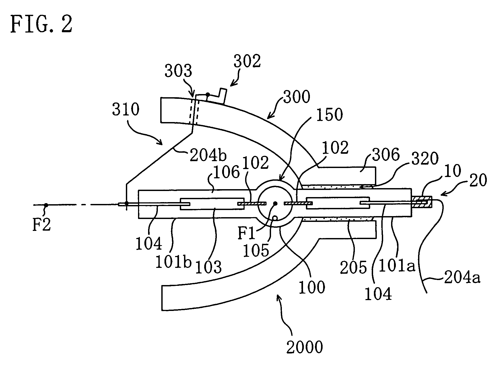
[0037]The embodiment of the present invention will be described with reference to FIGS. 2 and 3. FIG. 2 schematically shows a configuration of a reflecting-mirror-equipped lamp 2000 according to the embodiment.

[0038]The reflecting-mirror-equipped lamp 2000 of this embodiment is constituted by a high pressure discharge lamp 150 and a reflecting mirror 300. The high pressure discharge lamp 150 of this embodiment includes: a luminous bulb 100 enclosing a luminous material (e.g., mercury) 105 therein; and sealing portions 101a and 101b respectively extending from both ends of the luminous bulb 100. The high pressure discharge lamp 150 of this embodiment is a double-end type high-pressure mercury lamp and operates with alternating current.

[0039]...


PUM


Abstract

A reflecting-mirror-equipped lamp 2000 is constituted by a high pressure discharge lamp 150 and a reflecting mirror 300. The reflecting mirror 300 includes a wide opening 310 and a narrow opening 320. A first sealing portion 101a of the high pressure discharge lamp 150 is fixed near the narrow portion 320 of the reflecting mirror 300, and provided with no base. A second sealing portion 101b of the high pressure discharge lamp 150 is provided at a side of the wide opening 310 of the reflecting mirror 300. An external lead 104 of the first sealing portion 101a and an outward-drawn lead wire 204a are joined to each other by the plastic flow of a caulking member 10.

Description

BACKGROUND OF THE INVENTION[0001]The present invention relates to lamps with reflecting mirrors and image projecting apparatus. In particular, the present invention relates to a lamp with a reflecting mirror used as a light source of a liquid crystal projector or a light source of image projecting apparatus such as a digital micromirror device (DMD) projector.[0002]Image projecting apparatus such as liquid crystal projector devices are known as a means for magnifying and projecting images such as characters and figures to display the images. Such image display devices (or image projecting apparatus) need a predetermined optical output, so that reflecting-mirror-equipped lamps including high intensity discharge lamps (HID lamps) exhibiting high luminance are, in general, widely used as light sources. With widespread use of projectors, brighter and smaller projectors have been in demand.[0003]FIG. 8 schematically shows a cross-sectional configuration of a prior art reflecting-mirror-e...

Claims


Application Information

Patent Timeline
IPC IPC(8): F21V7/00F21S2/00F21V19/00G03B21/00F21V23/00F21Y101/00G03B21/14G03B21/20H01J5/52H01J61/02H01J61/36H01J61/86H04N9/31
CPCH01J5/52H01J61/025G03B21/2026H04N9/315H04N9/3197H01J61/36
Inventor HORIUCHI, MAKOTOICHIBAKASE, TSUYOSHISEKI, TOMOYUKI
Owner PANASONIC CORP
Why Eureka
Try Eureka