Attachment clip and attachment structure using same

a technology of attachment structure and attachment clip, which is applied in the directions of threaded fasteners, machines/engines, transportation and packaging, etc., can solve the problems of unsuitable attachment clip b>6/b> for components, and achieve the effect of suppressing the increase of manufacturing cost, easy rusting, and large contact area

Inactive Publication Date: 2006-02-14
NISSAN MOTOR CO LTD
View PDF5 Cites 19 Cited by
  • Summary
  • Abstract
  • Description
  • Claims
  • Application Information

AI Technical Summary

Benefits of technology

[0030]It is further noted that the above-mentioned attachment clip 6 comes into surface-contact with the heat shielding plate 4 due to the annular abutting part 6a annular-shaped with a predetermined width. Therefore, due to the largeness in contact area of the clip 10 with the heat shielding plate 4, the clip 10 is easy to produce rust easily.
[0031]Under the above circumstance, an object of the present invention is to provide an attachment clip which can be used even in a restricted installation space, such as underside of vehicle, and which can suppress increasing of the manufacturing cost with the characteristics of weight-saving, enhanced heat-resistance and rust-proof. Further, another object of the present invention is to provide an attachment structure using such an attachment clip.

Problems solved by technology

Therefore, the attachment clip 6 is unsuitable for attachment of components under restricted working circumstances such that the clip 6 attached to the lower face 1a of the vehicle body 1 might interfere with a road face.

Method used


Image

  • Attachment clip and attachment structure using same
  • Attachment clip and attachment structure using same
  • Attachment clip and attachment structure using same

Examples


Embodiment Construction

[0050]Referring to the accompanying drawings, an embodiment of the present invention will be described below.

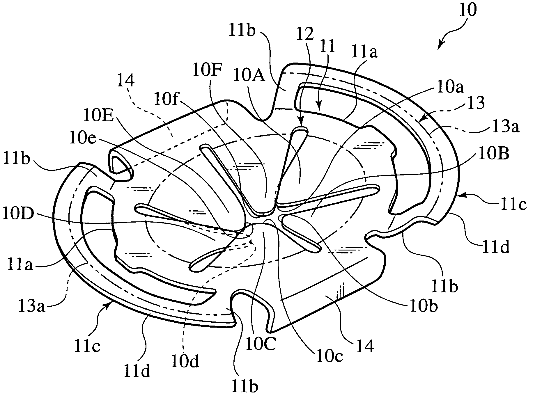
[0051]FIGS. 5 to 15 are views showing an attachment clip in accordance with the first embodiment of the present invention and an attachment structure using the above attachment clip.

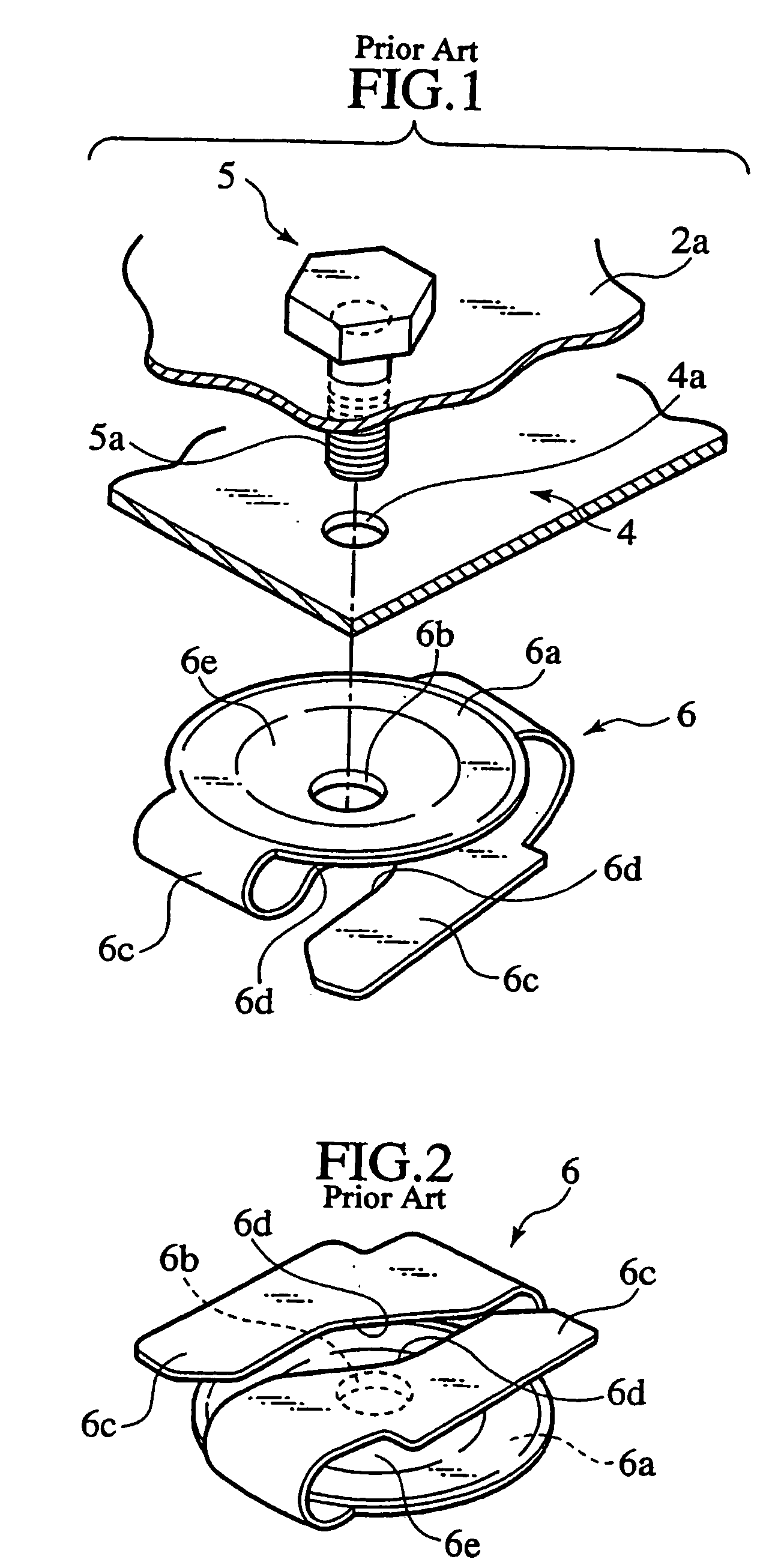
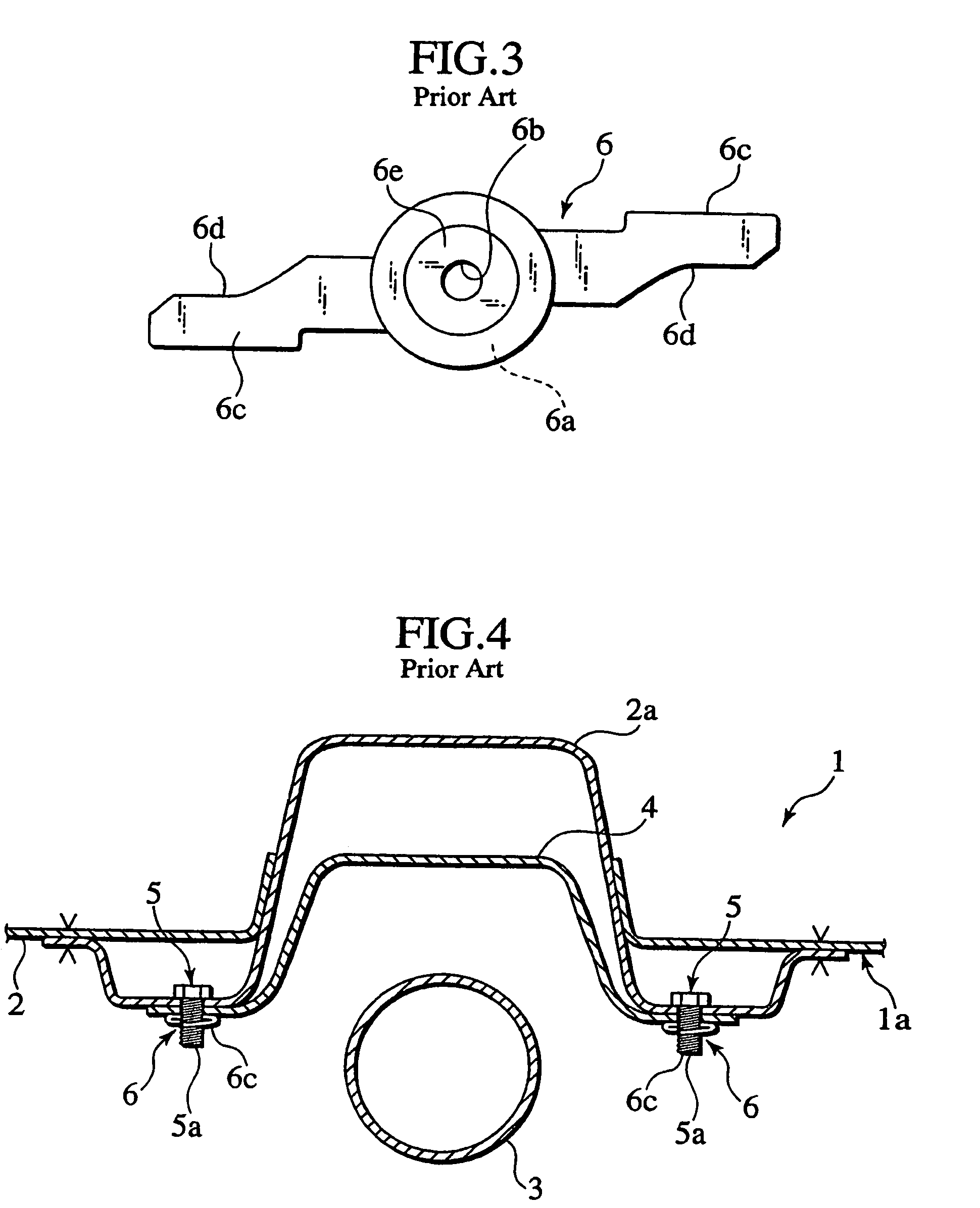
[0052]Noted that elements similar to those of the afore-mentioned clip and attachment structure in earlier technology are indicated with the same reference numerals, respectively.

[0053]In these figures, FIG. 5 shows the attachment clip of the first embodiment, while FIG. 6 shows a pair of attachment structures each using the attachment clip of FIG. 5.

[0054]In FIG. 6, similarly, a vehicle body 1a is provided, on its underside 1a, with an under-panel 2 as an “attached” member (the second member).

[0055]In the under-panel 2, a floor tunnel 2a is formed so as to swell upward at a substantial center in the width direction of the vehicle, having a hat-shaped section.

[0056]Attached below the floor tunnel ...


PUM


Abstract

An attachment clip 10 is provided to attach a heat shielding plate 4 to an under-panel 2. The under-panel 2 has a bolt 5 projecting from a floor tunnel 2a. The heat shielding plate 4 has a bolt hole 4a formed to allow passage of a shank 5a of the bolt 5. The attachment clip 10 has a clip body 11 having an abutting part 13 for abutment on the heat shielding plate 4. The abutting part 13 has a shank hole 12 for passage of the shank 5a of the bolt 5. The attachment clip 10 further includes six engagement claws 10A–10F projecting from the inner periphery of the clip body 11 inwardly. The engagement claws 10A–10F have respective engagement tips 10a–10f formed to depart from the clip body 11 along the axial direction of the attachment chip 10, providing a substantial cone-shaped configuration. The engagement claws 10A–10F elastically engage with threads of the shank 5a while urging the heat shielding plate 4 toward the under-panel 2 along the axial direction of the bolt 5.

Description

BACKGROUND OF THE INVENTION[0001]1. Field of the Invention[0002]The present invention relates to an attachment clip suitable for a vehicle and an attachment structure using the attachment clip.[0003]2. Description of Related Art[0004]FIGS. 1 to 4 show an attachment clip which is used to attach car components, such as heat shield plate for insulating heat of a muffler etc. underside the vehicle, that are apt to be influenced by heat.[0005]In the attachment structure using the attachment clip like this, a vehicle body 1a is provided, on its underside 1a, with an under-panel 2 as an “attached” member.[0006]In the under-panel 2, a floor tunnel 2a is formed so as to swell upward at a substantial center in the width direction of the vehicle, having a hat-shaped section.[0007]Attached below the floor tunnel 2a is a heat shield plate 4 which shields the under-panel 2 from heat of a muffler 3, as an “attaching” member.[0008]On the under-panel 2, bolts 5 are arranged to project downward throu...

Claims


Application Information

Patent Timeline
Patent Type & Authority Patents(United States)
IPC IPC(8): F16B37/16B60R13/08B62D25/20B62D27/06F01N13/14F16B37/02
CPCB62D25/2072B62D27/065F16B37/02F01N13/14B60R13/0861
Inventor NISHIKAWA, MASAHARU
Owner NISSAN MOTOR CO LTD
Why Eureka
Try Eureka