
Ultrasound clutter filtering with iterative high pass filter selection

a filtering and ultrasonic technology, applied in the field of filtering, can solve the problems of i/q data analysis being dominated, strong reflections of orders of magnitude, and weak echo return of moving blood, and achieve the effect of suppressing color flash artifacts without compromising low flow detection

Inactive Publication Date: 2006-02-14
SHENZHEN MINDRAY BIO MEDICAL ELECTRONICS CO LTD
View PDF72 Cites 23 Cited by
  • Summary
  • Abstract
  • Description
  • Claims
  • Application Information

AI Technical Summary

Benefits of technology

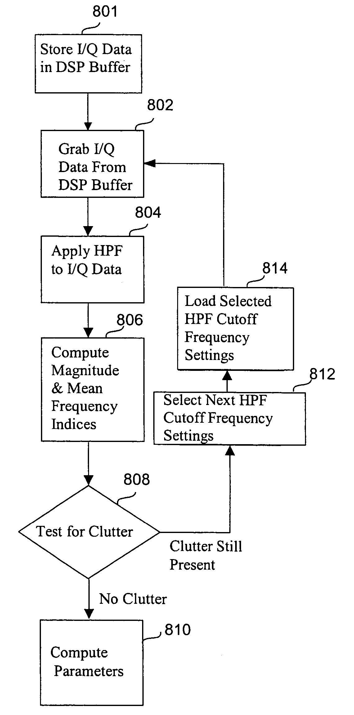
[0032]An adaptive clutter removal method is provided that can suppress color flash artifacts without compromising low flow detection. The method utilizes an adaptive high pass filter which is applied to the in-phase (I) and quadrature (Q) components of a given flow data packet prior to flow parameter estimation. The clutter may be detected a

Problems solved by technology

In practice, there are two significant challenges in producing a real-time color flow image.
First, the echoes returning from moving blood are generally very weak, so typically a packet of several or more transmit and receive cycles are needed to detect flow along a particular scan line.
The second practical challenge stems from the fact that the tissue medium, and especially bones and tissue layers that comprise the vessel walls of the insonified blood vessel, often produce very strong reflections that are orders of magnitude larger than the backscattered signals from blood.
Without first removing the clutter, the I / Q data analysis would be dominated by clutter effects and will not reflect the desired flow signal properties.
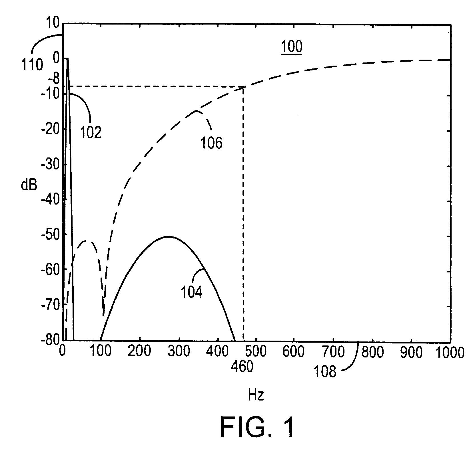
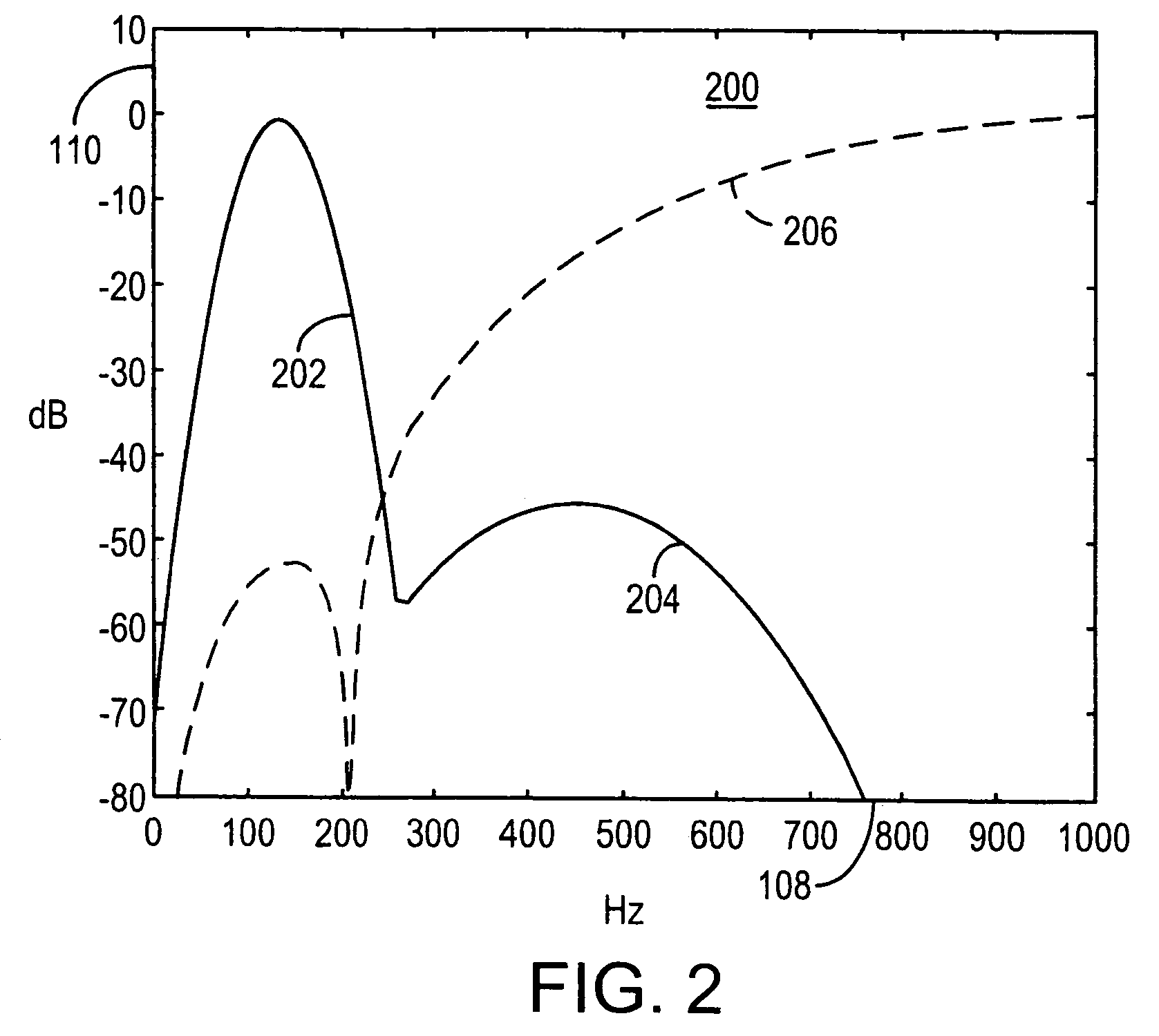
If the filter cutoff is always set high to reject the highest possible clutter frequencies, then some low flow signals may not be detected well.
If the filter cutoff frequency is always set low, color flashes may result in the image whenever significant clutter power due to tissue motion is present above the cutoff frequency.
Also, the standard autocorrelation method involves a division and an arctangent operation, which are computationally expensive.
In U.S. Pat. No. 5,228,009, as the order of filtering increases, the amount of computations required for computing the projection onto the basis function based on the least squares criterion also increases and is quite computationally intensive.
While it is true that in general, color flashes can be rejected by such post processing or other simpler threshold techniques based on the total power and mean velocity estimates, if a weaker flow signal is also present, it will likely get thrown out with the flash artifact.

Method used


Image

  • Ultrasound clutter filtering with iterative high pass filter selection
  • Ultrasound clutter filtering with iterative high pass filter selection
  • Ultrasound clutter filtering with iterative high pass filter selection

Examples


embodiment 500

[0057]FIG. 5 shows an embodiment 500 of ultrasound system 400 having a monitor 502, a keyboard 504, a mouse 506, a computing system 508, a transducer system 510, and cables 512. Monitor 502 may be touch sensitive or may be just for viewing. Monitor 502 is part of output system 402 (FIG. 4). If monitor 502 is touch sensitive, it is part of input / output system 414 (FIG. 4). Keyboard 504 and mouse 506 are part of input system 404 (FIG. 4), and are used to input text and / or select menu items, icons, virtual tabs and / or virtual buttons, for example. Computing system 508 includes processing system 408 and memory system 406 (FIG. 4). Transducer system 510 is part of transducer system 410, and is used for transmitting (generating and receiving) ultrasound signals to a medium under investigation such as a human body.

[0058]FIG. 6 shows another embodiment 600 of ultrasound system 400. Embodiment 600 has an imaging unit 604, a display and control unit 606, which may also be referred to as a Pro...

embodiment 600

[0059]Embodiment 600 is a hand-held device that can be operated with either hand 622 or 624. Ultrasound system 400 may be any type of handheld ultrasound imaging unit, such as that of U.S. Pat. No. 6,251,073.

[0060]Display and control unit 606 may be responsible for setting up, displaying, processing, storing, and annotating information gathered from imaging unit 604. The function of display and control unit 606 may include image reconstruction, color flow estimation, and Doppler computations, for example. Display and control unit 606 may include a Personal Digital Assistant (PDA). Display and control unit 606 may be battery operated, and screen 620 on display and control unit 606 may be touch sensitive. Handle 614 is for holding display and control unit 606. User interactions with display and control unit 606 may be through buttons 616 on handle 614 and / or touch sensitive control areas on screen 620. In an embodiment (not shown), handle 614 could be replaced with a small keyboard or...

embodiments 500 and 600

[0066]Embodiments 500 and 600 or any embodiment of ultrasound system 400 may provide a user interface that may include several intelligent (adaptive and context sensitive) active elements, e.g., windows, soft buttons, tabs, menus, toolbars, and / or icons.

[0067]In one embodiment, GUI 621 interface is voice controlled, and the user can train the device to recognize a set of words or combinations of words. Each recognizable unit (word or word combination) can be assigned to a device command, performing a specific function or a sequence of functions. Some or all functions can be voice activated obviating or partially obviating the use of hand controls. A similar GUI can be provided for embodiment 500 or any of the embodiments of ultrasound system 400.

[0068]FIG. 7A shows the main system block diagram 700 for an embodiment of ultrasound system 400 that supports B-mode and color flow imaging, input system 404, having a transducer array 710, a transmitter 711, a T / R 712, RF data 713, electro...


PUM


Abstract

A system and method for ultrasound clutter filtering is provided. A processor is configured to iteratively select an optimal high pass filter for the progressive, ordered filtering of clutter from ultrasound color flow imaging data. The high pass filter input for each iterative selection and ordered set of high pass filters is the same original ultrasound color flow imaging data. The high pass filters have different cutoff frequencies whereby each high pass filter can be implemented using different structures. The system and method allow for filtering of clutter from ultrasound color flow imaging data until the clutter is substantially removed.

Description

CROSS-REFERENCE TO RELATED APPLICATIONS[0001]This application is a continuation and claims the priority benefit of U.S. patent application Ser. No. 10 / 167,606 for a “System and Method for Adaptive Clutter Filtering in Ultrasound Color Flow Imaging” filed Jun. 11, 2002 and now U.S. Pat. No. 6,733,455; U.S. patent application Ser. No. 10 / 167,606 is a continuation-in-part of U.S. patent application Ser. No. 10 / 081,542 for a “User Interface for Handheld Imaging Devices” filed Feb. 20, 2002 and now abandoned which is a continuation-in-part of U.S. patent application Ser. No. 09 / 860,209 for a “Miniaturized Ultrasound Apparatus and Method” filed May 18, 2001 and now U.S. Pat. No. 6,569,102 which is a continuation of U.S. patent application Ser. No. 09 / 378,175 for a “Miniaturized Ultrasound Apparatus and Method” filed Aug. 20, 1999 and now U.S. Pat. No. 6,251,073; U.S. patent application Ser. No. 10 / 167,606 also claims the priority benefit of U.S. provisional patent application No. 60 / 370,6...

Claims


Application Information

Patent Timeline
IPC IPC(8): A61B8/06A61B8/00A61B8/08G01S15/89
CPCA61B8/00G01S15/8981A61B8/08A61B8/4438A61B8/462A61B8/465A61B8/467G01S7/52084A61B8/0833A61B8/0866A61B8/13A61B8/4455A61B8/468A61B8/488A61B8/06A61B8/4433
Inventor MO, LARRY Y. L.CHOU, CHING-HUAJI, TING-LANMCLAUGHLIN, GLEN W.
Owner SHENZHEN MINDRAY BIO MEDICAL ELECTRONICS CO LTD
Learn More