
Projection tube having different neck diameters

a technology of projection tube and neck diameter, which is applied in the direction of electrical connection of cathode-ray/electron beam tube, television system, and screen, etc., can solve the problems of small advantage obtained by reducing deflection power, not yet commercialized, etc., and achieve enhanced focus performance

Inactive Publication Date: 2006-02-14
HITACHI LTD +1
View PDF15 Cites 1 Cited by
  • Summary
  • Abstract
  • Description
  • Claims
  • Application Information

AI Technical Summary

Benefits of technology

[0009]A typical object of the present invention is to provide a single electron beam type projection tube operable at a high voltage which can reduce the deflection power thus enhancing the focusing performance.
[0011]In this aspect of the present invention, deflection power may be reduced and focusing performance may be enhanced.
[0013]Further, in the PRT, the improvement of the spherical aberration which occurs when the diameter of an electron lens is enlarged is more important than the improvement of the deterioration of focusing which occurs by the expansion of electron beams derived from the repulsion of the electron beams. That is, in the PRT, the effect of enlarging the diameter of the lens of the electron gun is more important than the effect of moving the electron gun farther from a phosphor screen by changing the neck diameter.
[0016]Due to such arrangement, a deflection circuit system can use a standard circuit for a neck of 29.1 mm and the focusing performance can be enhanced.

Problems solved by technology

The cathode ray tube disclosed in the above-mentioned U.S. Pat. No. 3,163,794 has not yet been commercialized because the maximum operating voltage used is so low that any advantage obtained by the reduction of the deflection power is small.
Further, since it is necessary to ensure a fixed dimension as the distance of the deflection yoke in the tube axis direction, when the outer diameter of a neck is set in two stages in an actual cathode ray tube, this causes an electron gun to be placed further from a phosphor screen due to mechanical restrictions.
Accordingly, increasing the total length of the cathode ray tube gives rise to disadvantages such as the deterioration of focusing performance.
Further, the cathode ray tube which is disclosed in the abovementioned Japanese Laid-open Patent Publication 185660 / 1999 has also not yet been commercialized.
Accordingly, it is difficult to provide a decrease in diameter of the neck and hence, the deflection sensitivity enhancing effect becomes extremely small.

Method used


Image

  • Projection tube having different neck diameters
  • Projection tube having different neck diameters
  • Projection tube having different neck diameters

Examples


Embodiment Construction

[0023]An embodiment of a projection tube having different neck diameters according to the present invention is explained hereinafter in conjunction with attached drawings.

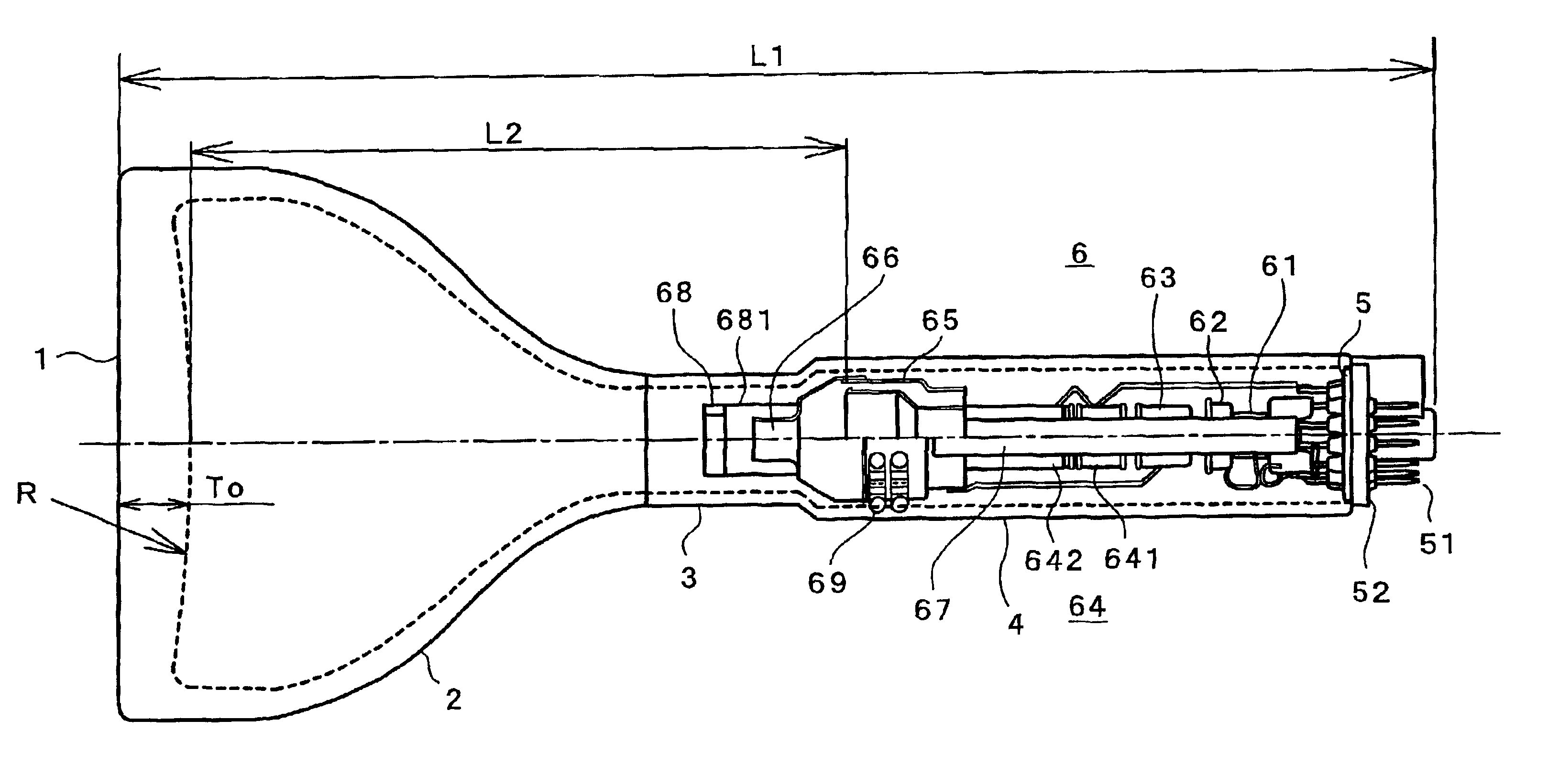
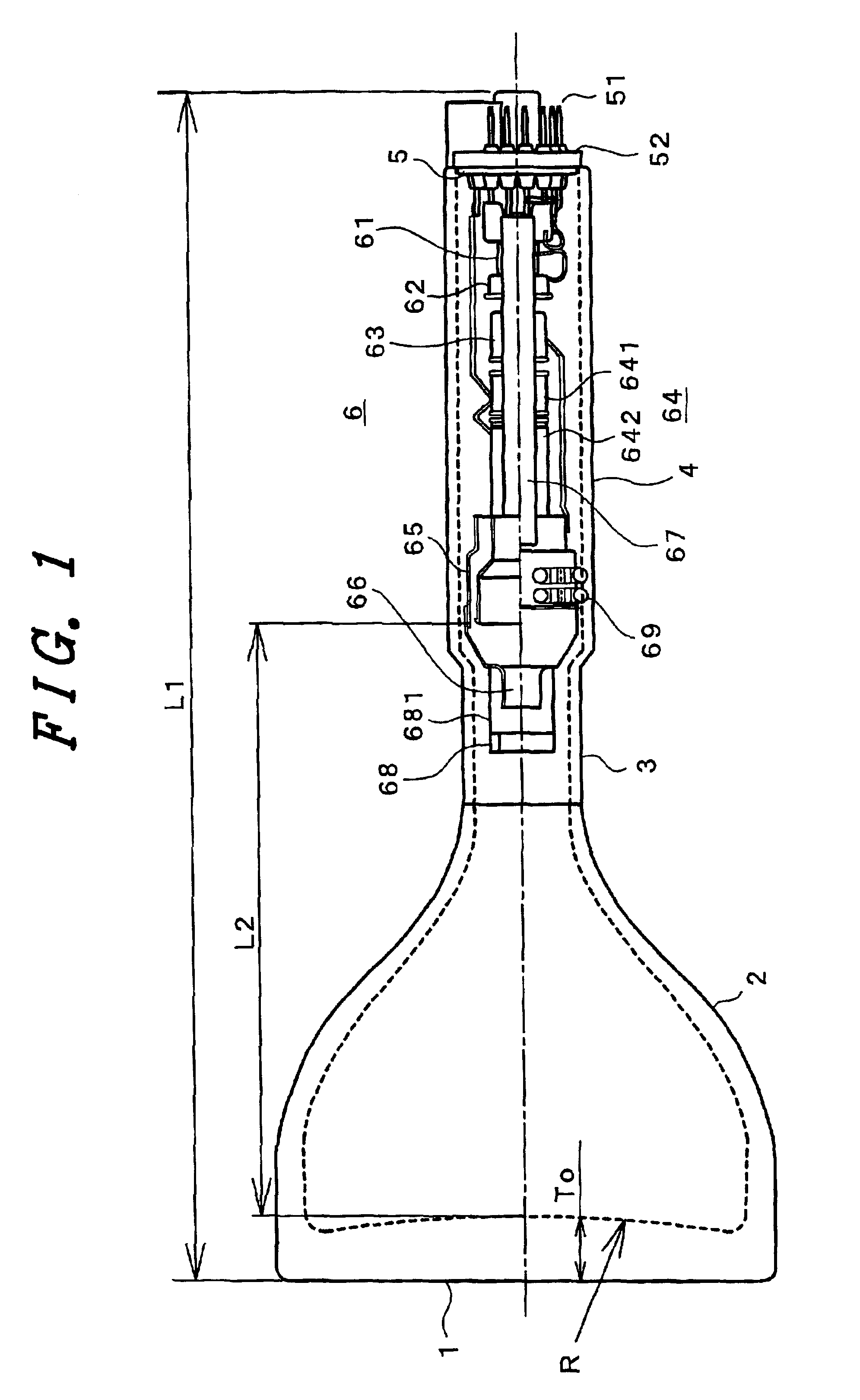
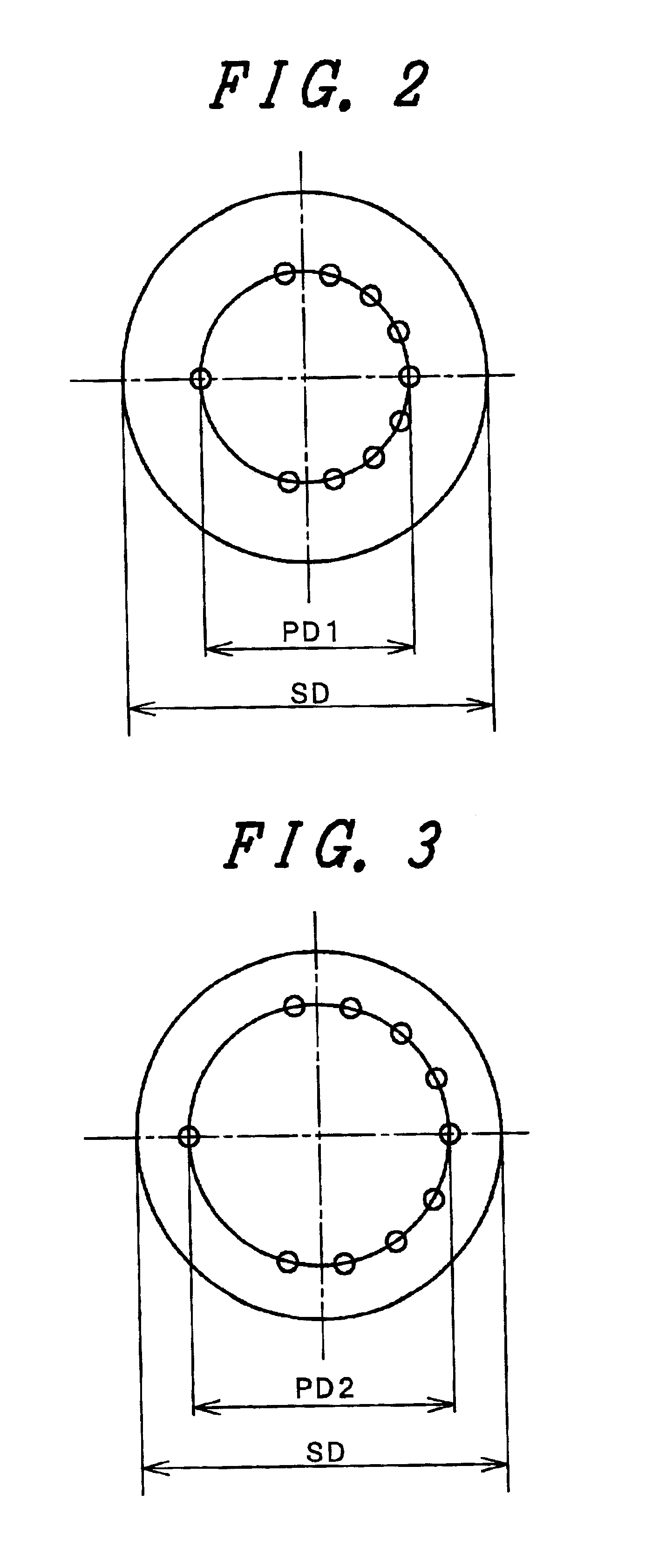
[0024]FIG. 1 is a schematic cross-sectional view of a cathode ray tube for a projection type TV receiver (PRT) of the present invention. When a monochromatic image is formed in the PRT only one electron beam is used. A panel 1 has a flat outer surface and an inner surface which is bulged toward an electron gun side forming a convex lens. In this embodiment, the inner surface of the panel 1 is formed in a spherical face having a radius R of curvature of 350 mm. To reduce the aberration, the inner surface may be formed in a non-spherical face. The thickness To of the panel 1 at the center thereof is 14.1 mm. The profile size of the panel 1 in the diagonal direction is set to 7 inches and the effective diagonal diameter which allows the formation of image is set to 5.5 inches. The total length L1 of the PRT is set to ...


PUM


Abstract

A projection tube having a high focusing performance at a low deflection power includes a funnel, a neck portion and a stem portion which seals the neck portion. The neck portion of the projection tube includes a first neck portion which is connected to the funnel and has a first neck outer diameter, and also includes a second neck portion which accommodates an electron gun and has a second neck outer diameter which is larger than the first neck outer diameter.

Description

BACKGROUND OF THE INVENTION[0001]1. Field of the Invention[0002]The present invention relates to a projection tube which is used in a projection type TV receiver, a video projector or the like.[0003]2. Description of the Related Art[0004]An image may be created by scanning an electron beam emitted from an electron gun onto a cathode ray tube via a deflection yoke. The deflection yoke is mounted near a joint portion, which is located between a neck and a funnel. The deflection sensitivity of the deflection yoke is increased when the outer diameter of the neck is decreased. However, when the outer diameter of the neck is decreased in order to enhance the deflection sensitivity, the electron gun which is accommodated in the neck portion must be miniaturized correspondingly. When the electron gun is miniaturized, the diameter of an electron lens of the electron gun is decreased and hence, focusing is degraded. Therefore, it can be seen from the above description that increasing the defl...

Claims


Application Information

Patent Timeline
IPC IPC(8): H01J29/86H01J9/24H01J31/00H01J29/90H01J31/10H04N5/74
CPCH01J29/861H01J2229/8606H01J9/24
Inventor SAITOU, KOUICHIHIRAI, KAZUMASAASANO, TETSUOAOKI, KOTAROTANAKA, YASUO
Owner HITACHI LTD
Learn More