Method for determining the mass moment of inertia of an electric motor drive system

a technology of electric motors and mass moments, applied in the direction of electric variable regulation, process and machine control, instruments, etc., can solve the problems of limiting accuracy, not achieving the desired effect of further optimizing control, and not achieving optimal results for all operational states

Inactive Publication Date: 2006-02-14
DR JOHANNES HEIDENHAIN GMBH
View PDF21 Cites 17 Cited by
  • Summary
  • Abstract
  • Description
  • Claims
  • Application Information

AI Technical Summary

Benefits of technology

[0014]Thus, the prior determination of the compensation current required for operating the drive mechanism at constant motor speed is a prerequisite for calculating the mass moment of inertia from the acceleration current. The compensation current is determined in that the drive mechanism is operated at least two different motor speeds, which are constant during a predetermined length of time and preferably have the same value, but opposite signs. The compensation current which is required for maintaining the motor speed constant at a predetermined value can be determined from this, i.e. which completely compensates losses occurring during the operation at constant motor speed, so that no reduction of the motor speed due to losses occurs.

Problems solved by technology

If the quotient lies outside the range wherein it allows a high-quality control, steps for further optimizing the control often do not bring the desired success.
However, an iterative method always has the disadvantage that it is limited with respect to its accuracy, and furthermore, because of its proneness to errors, it does not necessarily lead to an optimal result for all operational states.

Method used


Image

  • Method for determining the mass moment of inertia of an electric motor drive system
  • Method for determining the mass moment of inertia of an electric motor drive system
  • Method for determining the mass moment of inertia of an electric motor drive system

Examples


Embodiment Construction

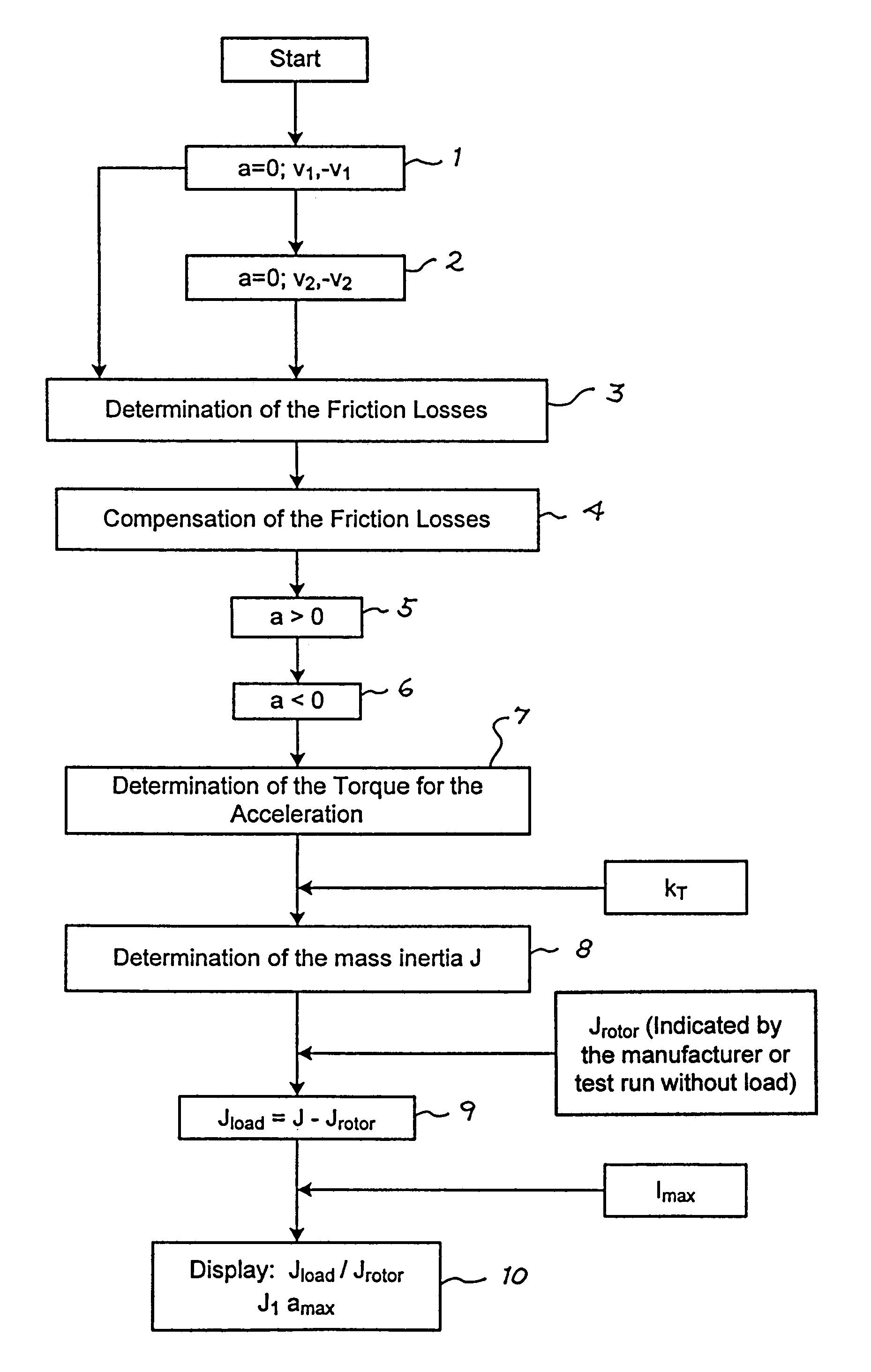
[0027]The following description of an exemplary embodiment of the method of the present invention by FIGS. 1 to 3 is based on an electric motor drive system for a machine tool, including a drive motor, as well as components connected downstream of the drive motor, such as, for example, a clutch, a ballscrew, gear elements and a table of the machine tool which is to be translationally moved. By determining the resultant mass moment of inertia of this drive system, it is possible to determine the quotient of the mass moment of inertia of the motor and the mass moment of inertia of the load. The mass moment of inertia of the motor is a constant which is known for the respective type of motor and is usually disclosed by the manufacturer. The mass moment of inertia of the load results from subtracting the mass moment of inertia of the motor from the mass moment of inertia of the drive system as a whole. This in turn makes possible the determination of the quotient of the mass moment of i...


PUM


Abstract

A method for determining the mass moment of inertia of an electric motor drive system of a machine, having a drive motor and further drive elements arranged downstream of the drive motor. The method includes a) determining a compensation current, which compensates losses occurring at a constant speed of the motor, so that a motor speed of the drive motor remains constant and b) determining an acceleration current, which generates a defined acceleration of the drive motor when the losses occurring at the constant speed of the drive motor are compensated. The method further entails c) calculating a mass moment of inertia of the electric motor drive system based on the determined acceleration current.

Description

[0001]Applicants claim, under 35 U.S.C. §119, the benefit of priority of the filing date of Aug. 8, 2002 of a German patent application, copy attached, Ser. No. 102 36 847.3, filed on the aforementioned date, the entire contents of which is incorporated herein by reference.BACKGROUND OF THE INVENTION[0002]1. Field of the Invention[0003]The present invention relates to a method for determining the mass moment of inertia of an electric motor drive system of a machine, in particular a machine tool, which includes a drive motor and further drive elements arranged downstream of the drive motor.[0004]2. Discussion of Related Art[0005]For assessing the dynamic machine layout, the ratio of the mass moment of inertia of the motor (which is related in a strict sense to the drive motor, i.e. its rotor, and which, in connection with a rotary drive mechanism, is equal to the mass moment of inertia of the rotor) to the mass moment of inertia of the load (which relates to the remaining components ...

Claims


Application Information

Patent Timeline
Patent Type & Authority Patents(United States)
IPC IPC(8): B64C17/02G05D13/00H02P7/00G01M15/00G01M1/10G01P3/42G01P15/00H02K7/02H02P5/00H02P29/00
CPCG01M1/10Y10S388/93
Inventor KERNER, NORBERTKELLNER, EUGEN
Owner DR JOHANNES HEIDENHAIN GMBH
Why Eureka
Try Eureka