Surface-mount crystal oscillator

a surface-mounted crystal oscillator and quartz crystal technology, which is applied in the direction of pulse generators, pulse generators, pulse techniques, etc., can solve the problems of reducing the thickness, design problems, and difficult maintenance of the space for mounting chip capacitors b>9/b>, so as to reduce the size of the crystal unit

Inactive Publication Date: 2006-02-14
NIHON DEMPA KOGYO CO LTD
View PDF6 Cites 24 Cited by
  • Summary
  • Abstract
  • Description
  • Claims
  • Application Information

AI Technical Summary

Benefits of technology

[0017]Because the thickness of the metal cover can be made smaller than the thickness of the frame walls of laminated ceramic, the size of the crystal unit can be reduced while maintaining the size of the crystal blank unchanged, whereby a compact surface-mount crystal oscillator can be constructed which maintains space for mounting electronic components on the mounting substrate.

Problems solved by technology

In a surface-mount crystal oscillator of the above-described construction, however, there is the problem that, with the development of ever-smaller devices, the space for mounting chip capacitors 9 becomes difficult to maintain, such as in a case in which the planar outer dimensions of the oscillator are reduced to a size of 3.2 mm×2.5 mm.
However, since the oscillation characteristics of a crystal blank improve with the increase in the outer dimensions of the crystal blank, decreasing the outer dimension of crystal blank 3 has an adverse effect on the oscillation characteristics of crystal blank and thus results in design problems.
Frame walls 4b are composed of ceramic, and reducing the thickness not only reduces strength, but also raises problems in fabrication.
Thus, in either case, reducing the size of crystal unit 1 is problematic, and a reduction of the outer dimensions of mounting substrate 2 thus prevents mounting of chip capacitors 9.

Method used


Image

  • Surface-mount crystal oscillator
  • Surface-mount crystal oscillator
  • Surface-mount crystal oscillator

Examples


Embodiment Construction

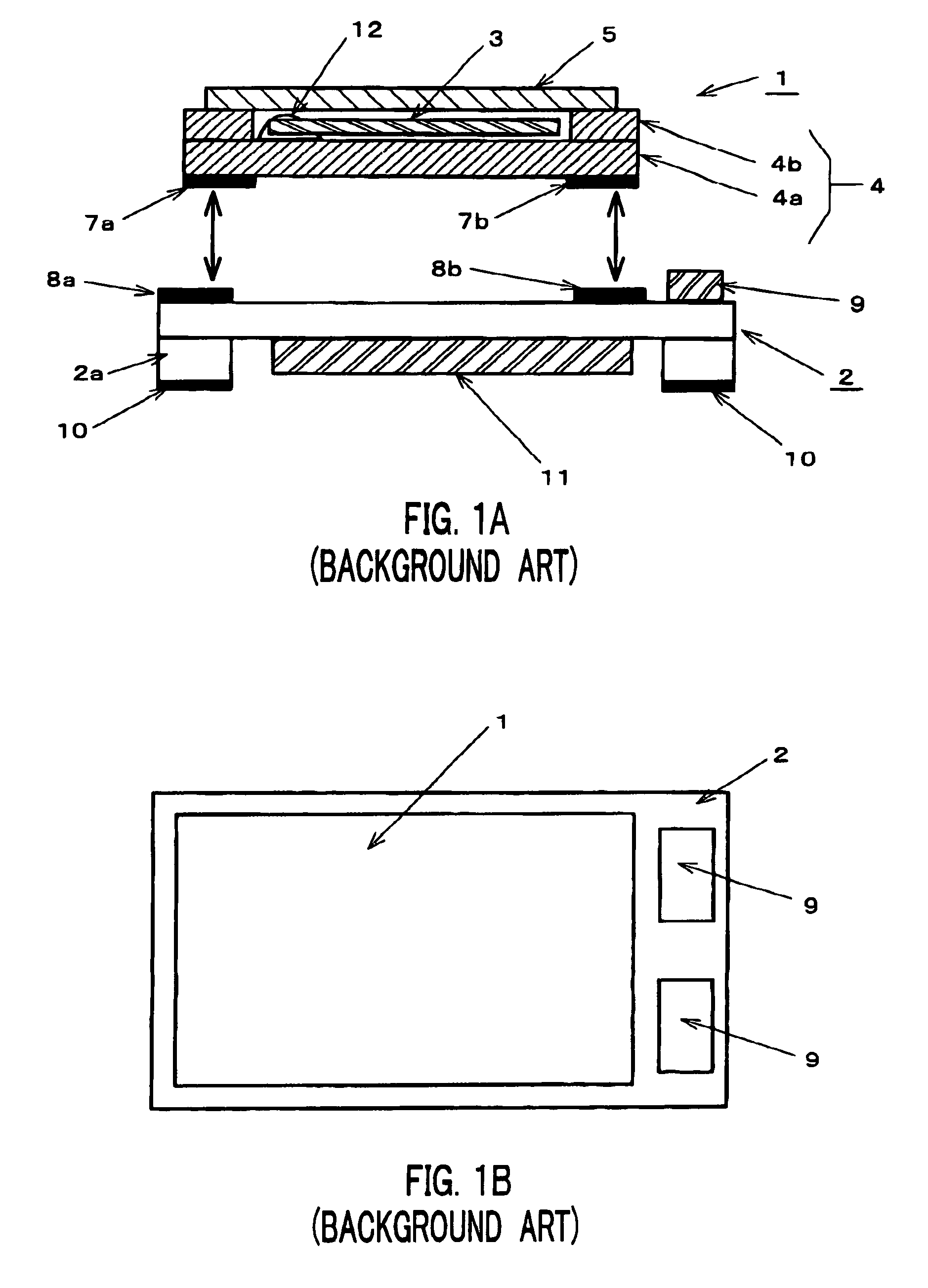
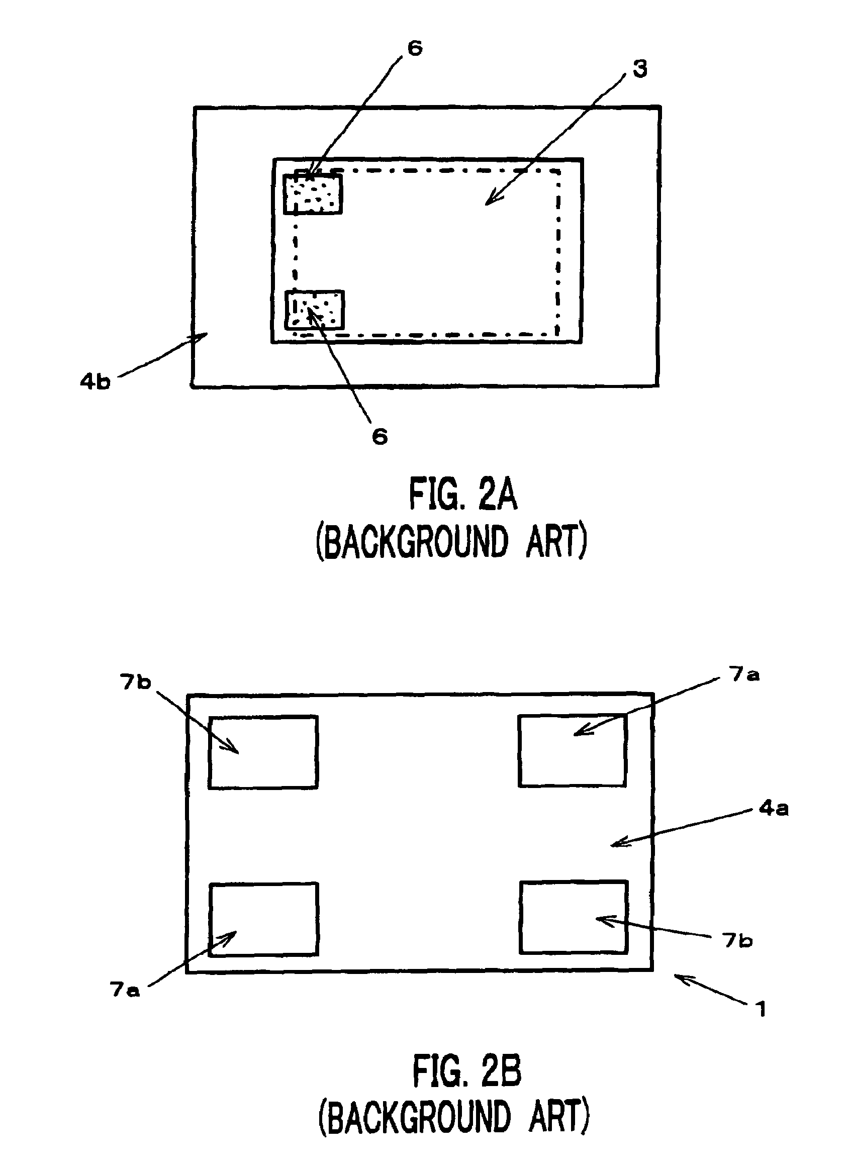
[0025]In FIGS. 3 and 4, which show a surface-mount crystal oscillator according to a preferable embodiment of the present invention, constituent elements which are identical to elements in the oscillator shown in FIGS. 1A, 1B, 2A, and 2B are identified by the same reference numerals, and redundant detailed explanation regarding these elements is not repeated here.

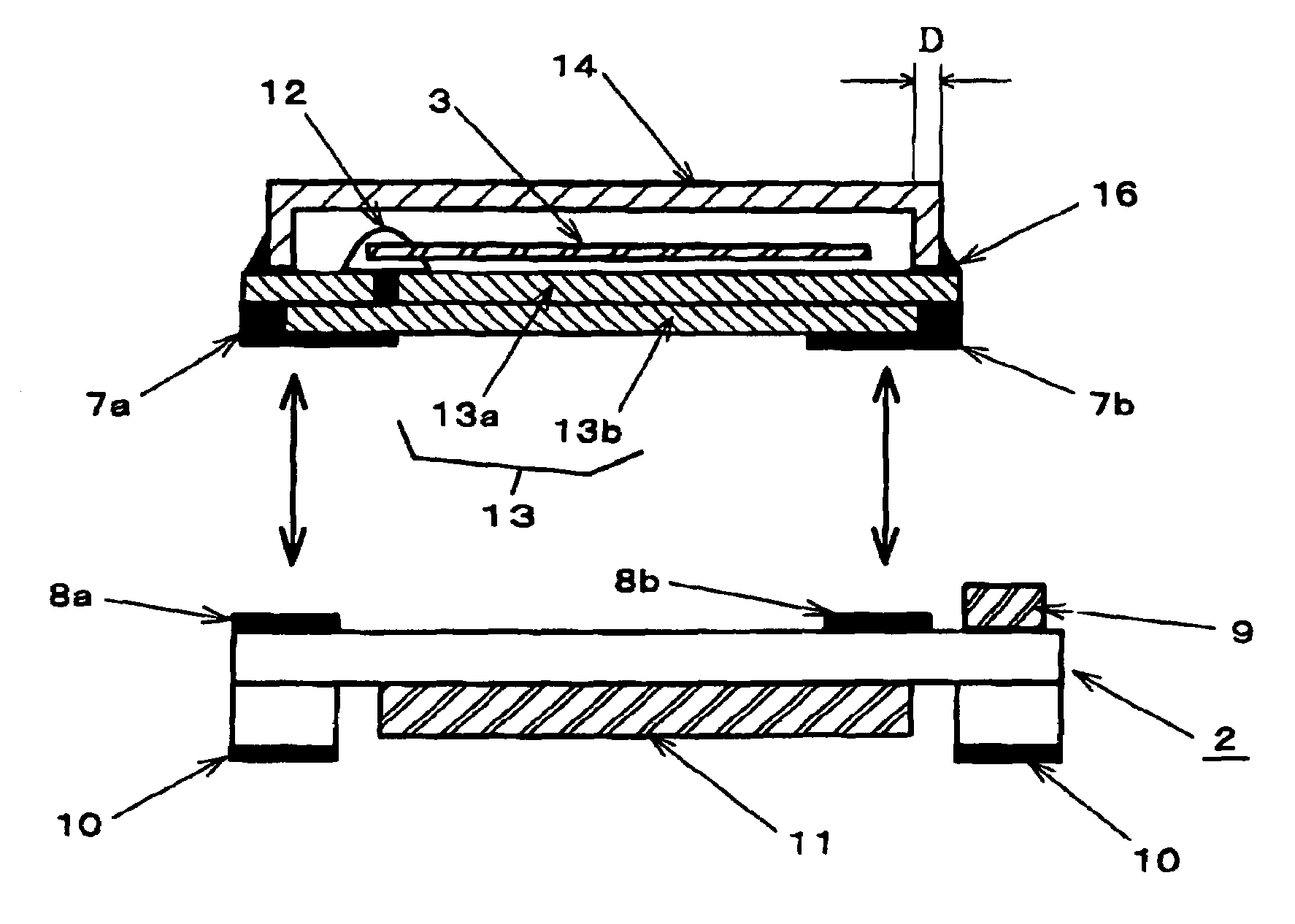
[0026]As previously described, in the surface-mount crystal oscillator according to the present embodiment, mounting substrate 2 which incorporates IC (Integrated Circuit) chip 11 is bonded to the rear surface of quartz crystal unit 1, and chip capacitors 9 are mounted on one end of mounting substrate 2. Crystal unit 1 used in this construction is made up from planar substrate 13, concave metal cover 14 which is provided to cover planar substrate 13, and quartz crystal blank 3 which is sealed between planar substrate 13 and metal cover 14. As in the previously described crystal oscillator of the prior art, a substantially r...


PUM


Abstract

A surface-mount crystal oscillator includes a quartz crystal unit, a mounting substrate on which an IC (Integrated Circuit) chip is mounted and which is bonded to the rear surface of the crystal unit, and an electronic components which is mounted on one end of the surface of the mounting substrate on which the crystal unit is bonded. The crystal unit includes a planar substrate, a quartz crystal blank held on one principal surface of the planar substrate, a metal film formed along the outer periphery of the principal surface, and a concave metal cover having an open-ended face. In the crystal unit, the open-ended face of the metal cover is brazed to the metal film, whereby the crystal blank is hermetically sealed between the metal cover and the planar substrate.

Description

BACKGROUND OF THE INVENTION[0001]1. Field of the Invention[0002]The present invention relates to a quartz crystal oscillator for supplying an oscillating frequency signal and which includes a quartz crystal unit and an IC (Integrated Circuit) chip that together with the crystal unit forms an oscillation circuit; and more particularly to a surface-mount crystal oscillator which is suitable for miniaturization wherein a mounting substrate, on which an IC chip is provided, is bonded to the rear surface of a crystal unit.[0003]2. Description of the Related Art[0004]Surface-mount crystal oscillators, and in particular, surface-mount temperature-compensated crystal oscillators (TCXOs) feature light weight, compact size, and an oscillation frequency having superior stability, and these devices are therefore widely used in communication equipment such as portable telephones which are used in a mobile environment. As one type of surface-mount crystal oscillator, there is a bonded-type surfac...

Claims


Application Information

Patent Timeline
Patent Type & Authority Patents(United States)
IPC IPC(8): H03B1/00H03B5/32H01L51/52H01L51/56
CPCH01L51/5237H01L51/56H10K50/84H10K71/00
Inventor HARIMA, HIDENORIMIZUMURA, HIROAKI
Owner NIHON DEMPA KOGYO CO LTD
Why Eureka
Try Eureka