Method and apparatus for detecting, mapping and locating underground utilities

a technology for underground utilities and mapping, applied in the direction of electromagnetic wave detection, instruments, measurement devices, etc., can solve the problems of routinely missed unexpected utilities, inaccurate utility depth information, and difficulty in recording

Inactive Publication Date: 2006-02-14
ENSCO INC
View PDF32 Cites 230 Cited by
  • Summary
  • Abstract
  • Description
  • Claims
  • Application Information

AI Technical Summary

Benefits of technology

[0012]A still further object of the present invention is to provide a novel and improved method and apparatus for detecting, rapidly mapping and then locating underground utilit

Problems solved by technology

This manual audio technique is subject to a number of problems.
Since at least an assumption of utility location is required, unexpected utilities are routinely missed.
An operator needs to be able to sort-out conflicting audio signals in complicated environments, and still errors can be made as signals jump from one utility to the next.
With this technique, utility depth i

Method used


Image

  • Method and apparatus for detecting, mapping and locating underground utilities
  • Method and apparatus for detecting, mapping and locating underground utilities
  • Method and apparatus for detecting, mapping and locating underground utilities

Examples


Embodiment Construction

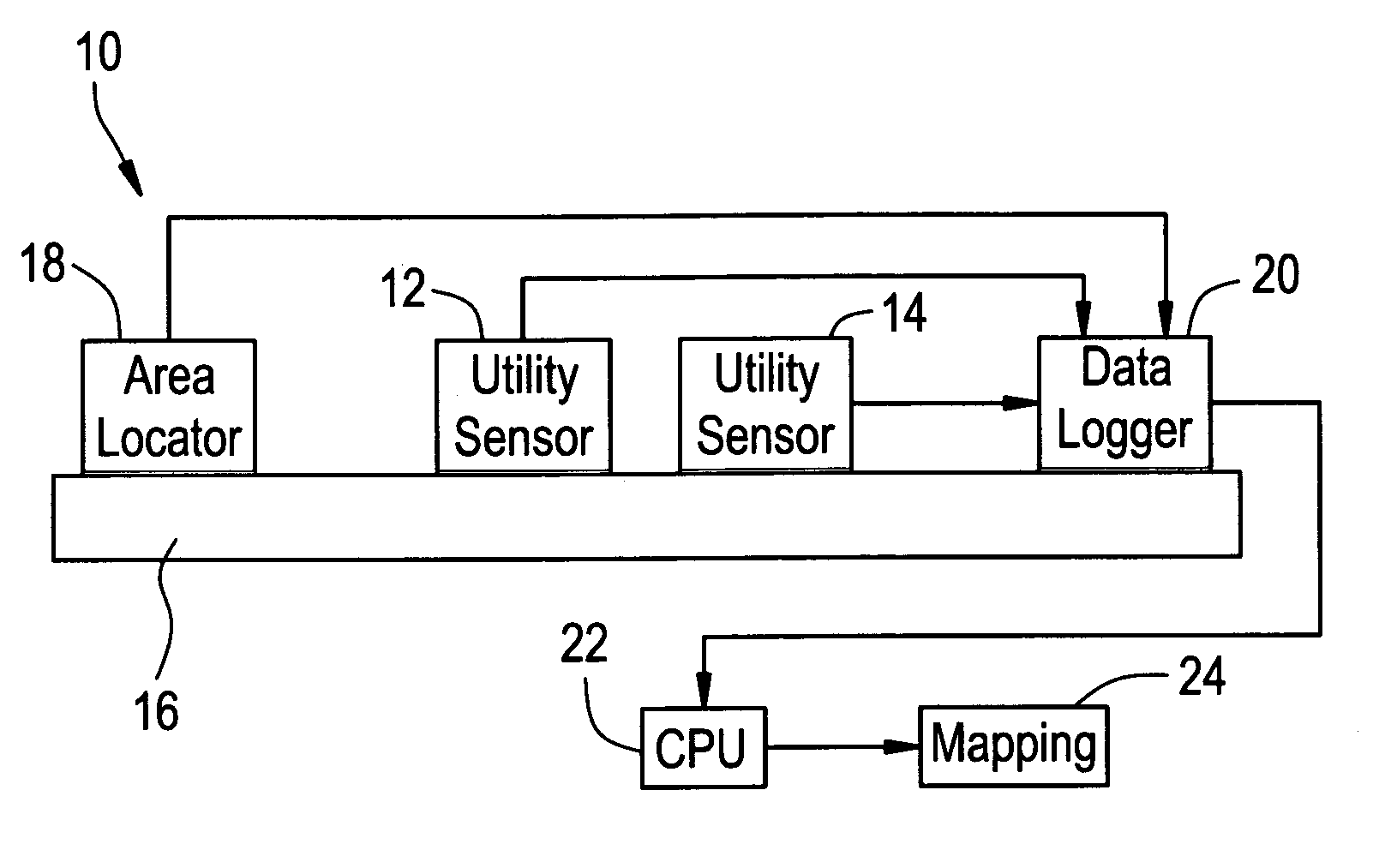
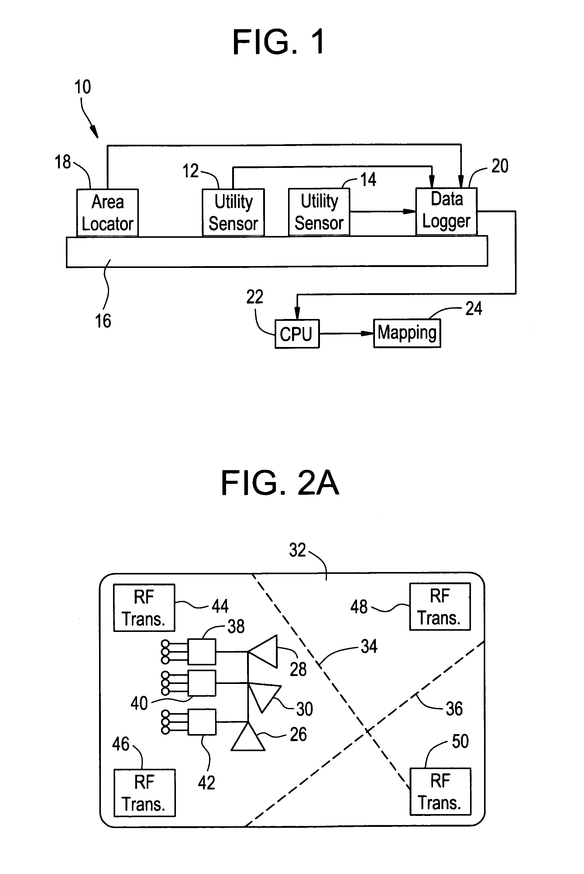
[0020]The apparatus for detecting, mapping and locating underground utilities of the present invention indicated generally at 10 includes a plurality of utility sensors 12 and 14 of different types in a sensor unit mounted on a movable support 16 with an area position locating system 18. Digital sensor data from the plurality of utility sensors is developed and stored with digital area position data developed from the area position locating system. This data is stored in a digital data logger 20 and combined in a post-processing data analysis that exploits the marriage of utility sensor with area position data to thereby allow provision of maps of underground utility location and depth within an area. This can be achieved by transferring data from the data logger to a processor 22 which provides data to a mapping unit 24.

[0021]The underground utility sensors of the sensor unit could include electromagnetic sensors (such as a Geonics EM61), magnetic sensors (such as a Geometrics G-85...


PUM


Abstract

The method and device for locating underground utilities within an area includes traversing the area with a plurality of underground utility sensors and obtaining area location data to locate the area traversed. The sensor data and area location data are used to map the location of one or more utilities within the area traversed.

Description

[0001]This application is based upon provisional application Ser. No. 60 / 274,617 filed Mar. 12, 2001.FIELD OF THE INVENTION[0002]The present invention provides for the detection, mapping and locating of underground utilities such as gas, electric, telephone, water, etc. using multiple sensors to provide spatially registered digital sensor data from which spatially registered positions of underground utilities can be determined.BACKGROUND OF THE INVENTION[0003]Conventional practice for locating underground utilities involves a manual, audio technique where a technician using a hand-held sensor with audio feedback first assumes where the target utility is located so that he can place a sensor on the assumed location to manually track the location of a utility based upon the audio feedback. The technician then makes paint marks on the ground over the underground utility so that this location can be subsequently mapped and so that an excavator can see the expected location of the utilit...

Claims


Application Information

Patent Timeline
IPC IPC(8): G01V3/12G01S13/89G01S13/88G01V3/15
CPCG01V3/15G01S13/89G01S13/885
Inventor TAYLOR, JR., DAVID W. A.BELL, ALAN G. R.ROLLAND, JOHN S.MCGARVEY, MATTHEW W.MCBRIDE, WILLIAM H. A.ROSENBERG, YURIFIELDS, GEORGE R. A.FAULKNER, WILLIAM T.
Owner ENSCO INC
Why Eureka
Try Eureka