Liquid cooling system

a cooling system and liquid cooling technology, applied in indirect heat exchangers, lighting and heating apparatus, instruments, etc., can solve the problems of increasing heat dissipation, liquid circulating within the system, and dissipating heat without power, and achieve the effect of convenient manufactur

Inactive Publication Date: 2006-02-14
QNX COOLING SYST
View PDF18 Cites 74 Cited by
  • Summary
  • Abstract
  • Description
  • Claims
  • Application Information

AI Technical Summary

Benefits of technology

[0016]A method of liquid cooling is presented. In one embodiment, a two-piece detachable liquid cooling system is presented. The two-piece detachable liquid cooling system facilitates easy manufacture. In addition, the unit is strategically designed to occupy a small amount of space within the limited area of a computing system housing.
[0020]In one embodiment, a first liquid momentum is generated by intaking a cooled liquid at a location in a heat transfer unit, transforming the cooled liquid to heated liquid by heating the cooled liquid in the heat transfer unit, and expelling the heated liquid from a position above the location used for intaking the cooled liquid. The first liquid momentum helps to circulate liquid in the liquid cooling system.
[0021]A second liquid momentum is generated by intaking the heated liquid at a location, cooling the heated liquid in a heat exchange unit, and expelling the cooled liquid from a location that is below the location used to intake the heated liquid. The second liquid momentum combines with the first liquid momentum to circulate the liquid in the liquid cooling system. The combination of the first liquid momentum and the second liquid momentum (i.e., convective liquid circulation) results in cooling even after power to the computing system has been shut down and virtually eliminates hot start problems. The convective liquid circulation also helps to eliminate a rapid rise processor temperature just after a processor has been shut down, which is a common occurrence in prior art processors. Further, convective liquid circulation enhances the forced liquid circulation resulting from the use of the pump and allows the system to recycle the heat into a physical force to move liquid through the system. Lastly, the convective liquid circulation allows the system to be more efficient by consuming less electrical power during operation. In one embodiment, as little as 5.7 watts of power is required to operate the liquid cooling system.

Problems solved by technology

Using the methods in combination results in heat dissipation that is exponentially greater than using each method individually.
As a result, liquid circulates within the system and dissipates heat without power.

Method used


Image

  • Liquid cooling system
  • Liquid cooling system
  • Liquid cooling system

Examples


Embodiment Construction

[0037]While the present invention is described herein with reference to illustrative embodiments for particular applications, it should be understood that the invention is not limited thereto. Those having ordinary skill in the art and access to the teachings provided herein will recognize additional modifications, applications, and embodiments within the scope thereof and additional fields in which the present invention would be of significant utility.

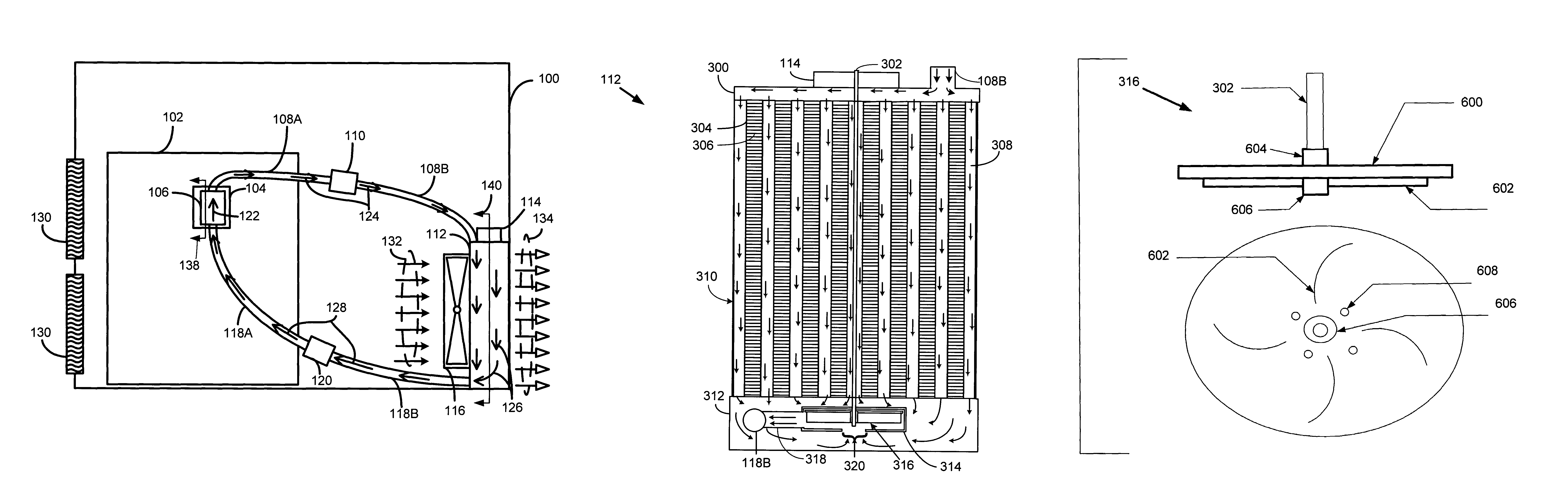
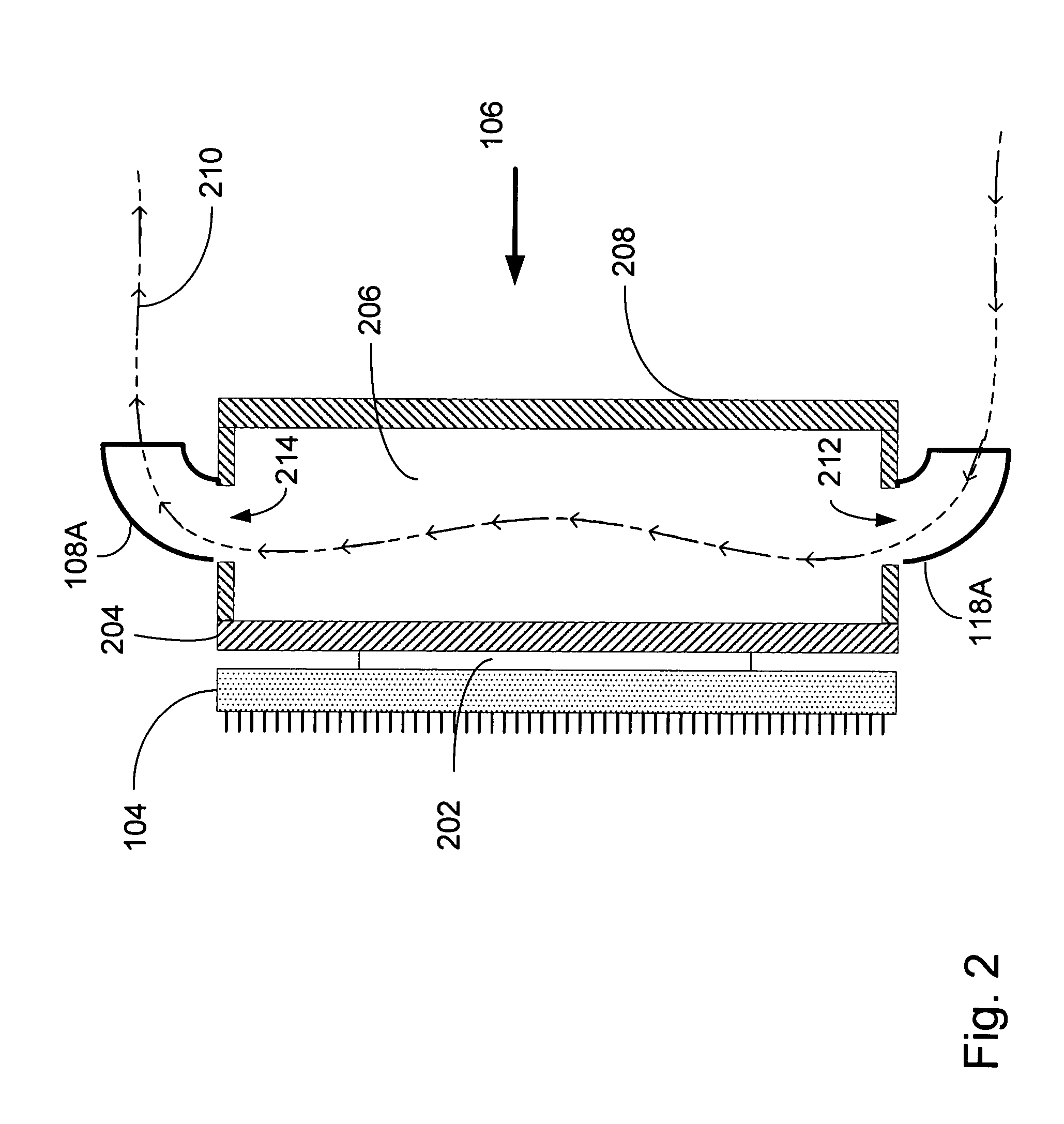
[0038]In one embodiment of the present invention, a two-piece liquid cooling system is presented. The two-piece liquid cooling system includes: (1) a heat transfer unit, which is capable of attachment to a processor, and (2) a heat exchange unit. In one embodiment, a single conduit is used to couple the heat transfer unit to the heat exchange unit. In a second embodiment, an input conduit transporting heated liquid and an output conduit transporting cooled liquid are used to couple the heat transfer unit to the heat exchange unit. It ...


PUM


Abstract

A liquid cooling system and apparatus is presented. A two-piece embodiment is presented. The first component is a heat transfer unit capable of engaging a processor and adapted to transfer heat from the processor to a liquid thereby generating heated liquid. The heated liquid is transported through a detachable input and output transport conduit to a second component. The second component is a heat exchange unit capable of cooling the liquid transported from the heat transfer unit. The heat exchange unit includes an input cavity for receiving the heated liquid, a heat dissipater for dissipating heat from the heated liquid thereby producing cooled liquid, and an output cavity for outputting the cooled liquid back to the heat transfer unit. In one embodiment, the heat exchange unit includes a pumping system for pumping the liquid from the heat exchange unit through the conduit to the heat transfer unit and back.

Description

BACKGROUND OF THE INVENTIONDescription of the Related Art[0001]Processors are at the heart of most computing systems. Whether a computing system is a desktop computer, a laptop computer, a communication system, a television, etc., processors are often the fundamental building block of the system. These processors may be deployed as central processing units, as memories, controllers, etc.[0002]As computing systems advance, the power of the processors driving these computing systems increases. The speed and power of the processors are achieved by using new combinations of materials, such as silicon, germanium, etc., and by populating the processor with a larger number of circuits. The increased circuitry per area of processor as well as the conductive properties of the materials used to build the processors result in the generation of heat. Further, as these computing systems become more sophisticated, several processors are implemented within the computing system and generate heat. I...

Claims


Application Information

Patent Timeline
Patent Type & Authority Patents(United States)
IPC IPC(8): H05K7/20F28D1/04F28D1/053F28F13/12G06F1/20H01L23/473
CPCF28D1/0535F28F13/125G06F1/20G06F1/203H01L23/473H05K7/20009G06F2200/201H01L2924/0002H01L2924/00
Inventor HAMMAN, BRIAN A.
Owner QNX COOLING SYST
Why Eureka
Try Eureka