Method and apparatus for spatial energy coverage

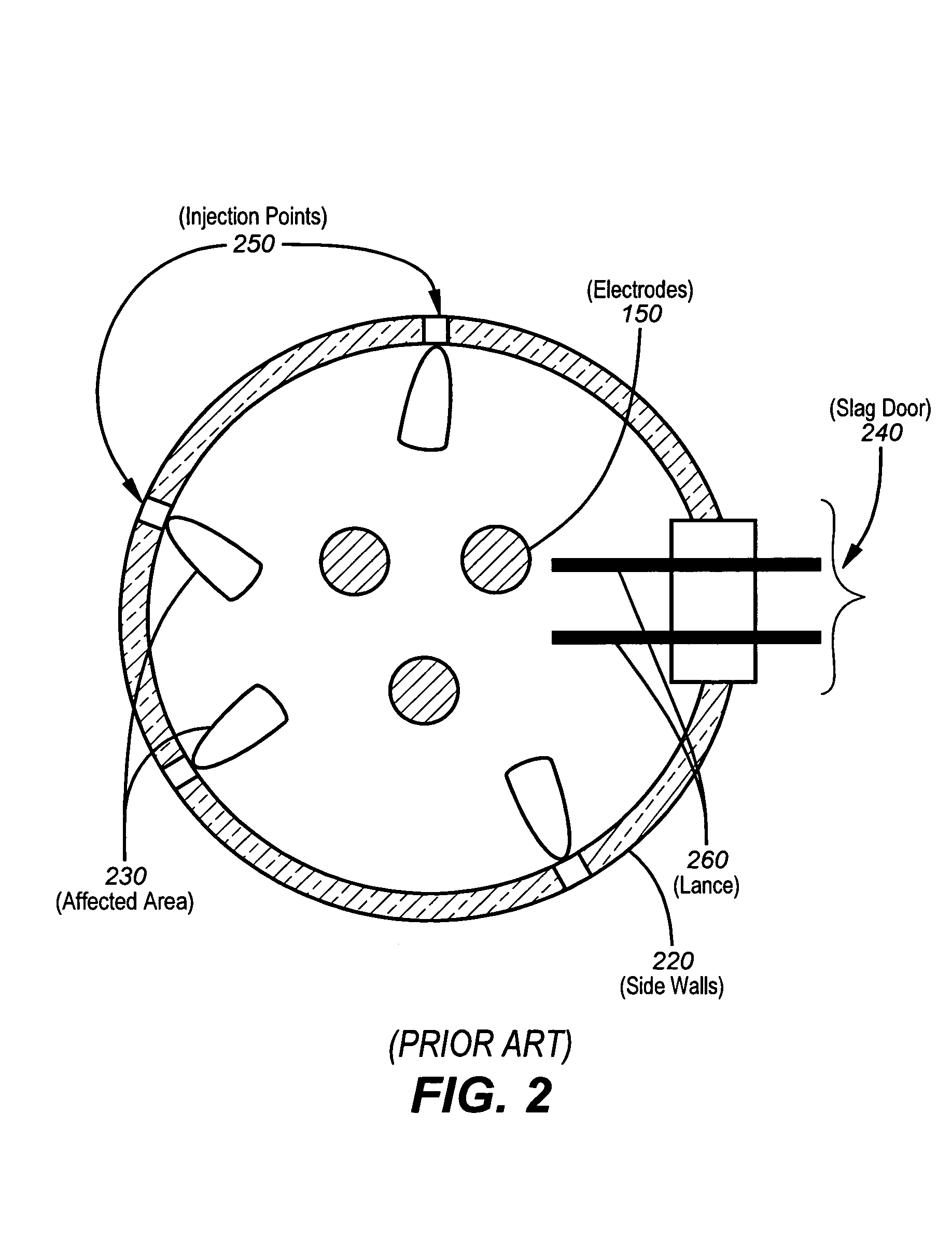
a technology of spatial energy and energy coverage, which is applied in the direction of lighting and heating equipment, electric furnaces, furnaces, etc., can solve the problems of insufficient melting of scrap between injection points b>250/b>, insufficient impact of chemical energy on scrap, and very spatial limitation of chemical energy input in the furnace, etc., to achieve the effect of increasing the spatial energy coverage of furnaces

Active Publication Date: 2006-02-14
LAIR LIQUIDE SA POUR LETUDE & LEXPLOITATION DES PROCEDES GEORGES CLAUDE +1
View PDF20 Cites 31 Cited by
  • Summary
  • Abstract
  • Description
  • Claims
  • Application Information

AI Technical Summary

Benefits of technology

[0022]In one aspect of the present invention, an apparatus for increasing spatial coverage of energy in a furnace is provided. The apparatus of the present invention includes a panel positioned at least partially into a sidewall of a furnace. The panel includes a plurality of openings for injecting a material through each of the openings at least partially during the same time period.
[0023]In yet another aspect of the present invention, an electric arc furnace is provided for increasing spatial coverage of energy in a furnace. The electric arc furnace of the present invention includes a roof, an upper shell, and a lower shell. The upper shell includes a furnace portion enclosed by a sidewall. The electric arc furnace of the present invention also includes a panel that is positioned at least partially into the sidewall of the furnace. The panel includes a plurality of openings for injecting a material through each of the openings at least partially during the same time period.
[0024]In another aspect of the present invention, a method for increasing spatial energy coverage in a furnace is provided. The method of the present invention includes positioning a panel at least partially within a sidewall of the furnace. The method also includes at least partially injecting during the same time period, a primary combustion material, a secondary combustion material, and a particulate material, into the furnace.

Problems solved by technology

As described above, one problem associated with state-of-the art implementation that the effect of chemical energy input in the furnace 100 is very spatially limited.
However, this implementation only provides these benefits in a limited, localized region.
However, immediately on the sides of the burner 260, scrap is not adequately affected by the chemical energy.
As a result, scrap between injections points 250 may not become adequately melted.
Since the ultimate goal of the process is to melt the entire scrap content of the furnace 100, the inefficiency in the current processes will cause the entire process to be performed at a much slower rate.
Furthermore, the improperly melted scrap may fall in the melted steel bath and will cool down the molten bath.
This solution, however, has reached its limits.
In order to perform the carbon injection via the opened slag door 240, manual operations are generally required, which can be dangerous.
Also, foaming is limited to the area in front of the furnace door.
With such practices, oxidized slag is immediately and continuously lost through the door immediately decreasing the yield of the process.
Various problems are associated with the implementation of the current methodology.
Therefore, current practices generally lead directly to a partial waste of the carbon.
In addition, un-burned carbon will eventually be dissociated into CO.
The increase in CO level in the exhaust gas is an undesirable effect.
Additionally, the increase in the CO level may generate combustion, explosion, increase in temperature, leading to problems in the water-cooled duct and bag-house.
If the carbon injection is introduced before the scrap is completely melted, the foaming slag may lead to slag-coating that may attach to un-melted scraps, preventing them from correct melting.
This un-melted scrap may eventually form skulls sticking to the furnace walls.
During the refining period, the skulls will eventually cave-in, which may cause strong, uncontrolled endothermic reactions.
These reactions can be dangerous and may damage portions of the furnace 100, including the electrodes 150.
Such reactions interrupt the steelmaking process and cool down the bath.
Furthermore, these reactions may generate additional CO in the exhaust gas, which may cause additional problems described above.
As a consequence, using state-of-the-art technologies, the furnace operators generally delay the start of carbon injection.
However, this early oxygen injection may generate locally high FeO content in the slag, strong mixing, and high temperature as the result of exothermic reactions.
Simultaneous carbon injections may reduce the locally high FeO content due to the early oxygen injection process; however, operators are reluctant to perform early carbon injection using state-of-the-art technology because of highly undesirable consequences described above.
The strong agitation, the high level of chemical reactions, and locally high temperature level results, generally lead to refractory erosion.
Therefore, such a limitation results in yet another loss of efficiency in steelmaking processes.
However, one problem associated with such a process is the resulting direct erosion of the brick locally.
Additionally, existing devices for injection through the refractory walls 360 have a limited life span, requiring a special system of cooling and require a specific quality of refractory for installation.
These steps also adversely affect process efficiency.
Slag splashing of the burner / lance head 330 may cause plugging problems.
As described above, various problems and inefficiencies are present due to the implementation of current methodology.

Method used


Image

  • Method and apparatus for spatial energy coverage
  • Method and apparatus for spatial energy coverage
  • Method and apparatus for spatial energy coverage

Examples


Embodiment Construction

[0039]Illustrative embodiments of the invention are described below. In the interest of clarity, not all features of an actual implementation are described in this specification. It will of course be appreciated that in the development of any such actual embodiment, numerous implementation-specific decisions must be made to achieve the developer's specific goals, such as compliance with system-related and business-related constraints, which will vary from one implementation to another. Moreover, it will be appreciated that such a development effort might be complex and time-consuming but would nevertheless be a routine undertaking for those of ordinary skill in the art having the benefit of this disclosure.

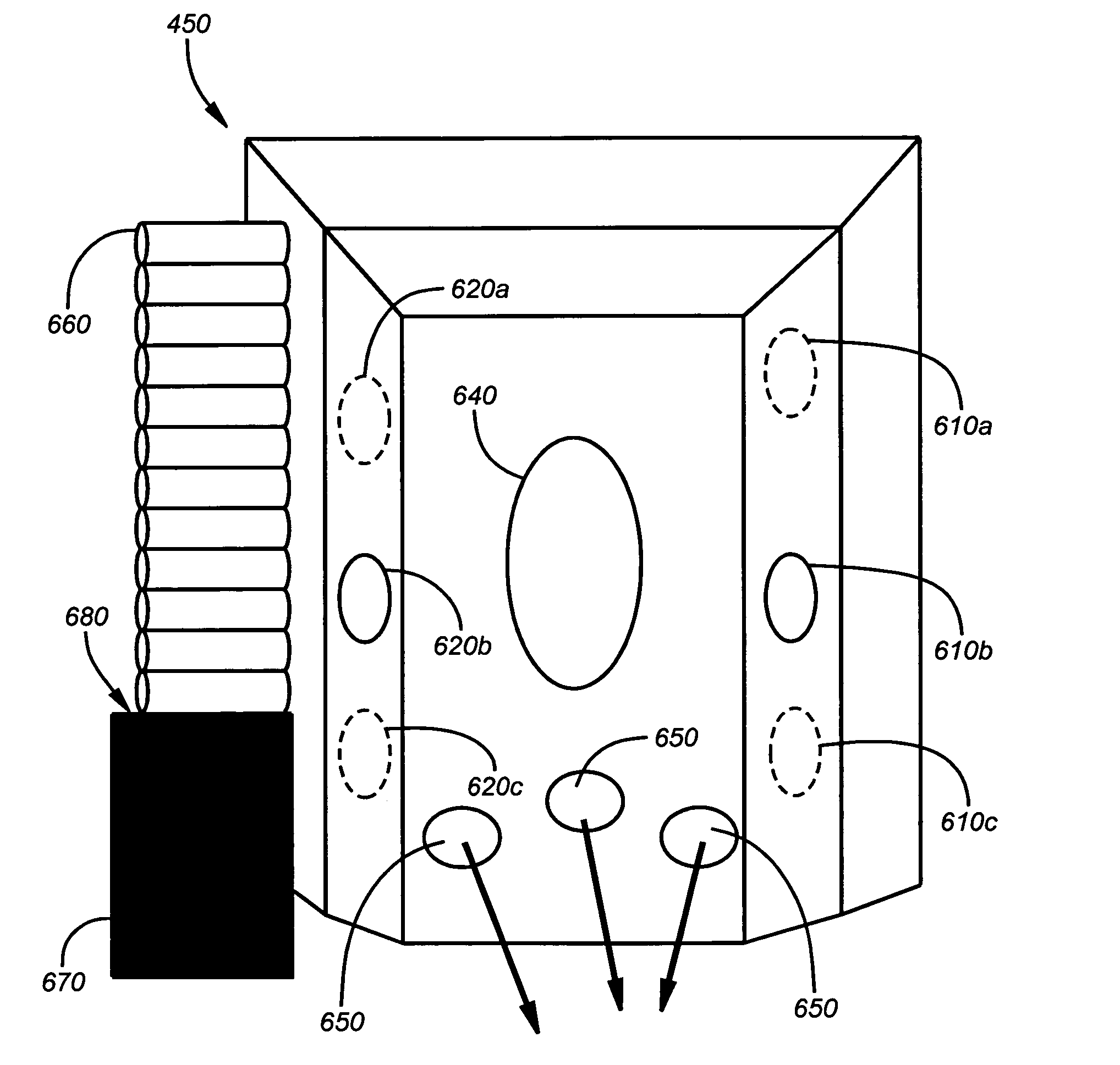
[0040]Embodiments of the present invention provide for implementing chemical energy more efficiently into an electric arc furnace. Embodiments of the present invention may be used to inject fuel, oxygen, carbon and other materials to increase the energy within an electric arc furn...


PUM

PropertyMeasurementUnit
angleaaaaaaaaaa
angleaaaaaaaaaa
diameteraaaaaaaaaa

Abstract

A method and apparatus for increasing spatial energy coverage in a furnace is provided. The apparatus of the present invention includes a panel positioned at least partially into a sidewall of a furnace. The panel includes a plurality of openings for injecting a material through each of the openings at least partially during the same time period. The method of the present invention includes positioning the panel at least partially within the sidewall of a furnace. The method also includes injecting at least partially during the same time period, a primary combustion material, a secondary combustion material, and a particulate material, into the furnace.

Description

CROSS REFERENCE TO RELATED APPLICATIONS[0001]This application claims the benefit of U.S. Provisional Application No. 60 / 434,922, filed Dec. 19, 2002, the entire contents of which are incorporated herein by reference.BACKGROUND OF THE INVENTION[0002]1. Field of the Invention[0003]This invention relates to electric arc furnace steelmaking systems and, in particular, to an apparatus and a method for increasing spatial coverage of chemical energy in such a furnace.[0004]2. Description of the Related Art[0005]There has been much advancement in the art of electric arc furnace steelmaking that has produced more efficient methods for producing steel products. Steelmakers have generally strived to increase the efficiency of processes used in steelmaking processes. In the quest for more efficient processes, higher amounts of energy are desired in electric arc furnaces during the various stages of the steelmaking processes. Those stages are generally divided in the heating / melting stage and on...

Claims


Application Information

Patent Timeline
Patent Type & Authority Patents(United States)
IPC IPC(8): F27D1/00C21C5/52F27B3/20F27B3/24
CPCC21C5/5217F27B3/24F27B3/205Y02P10/20
Inventor POPENOV, ALEXKAMPEN, PETER VANEYFA, YURYDELABROY, OLIVIER
Owner LAIR LIQUIDE SA POUR LETUDE & LEXPLOITATION DES PROCEDES GEORGES CLAUDE
Why Eureka
Try Eureka