Method and apparatus for testing echo canceller performance

a technology of echo canceller and performance, applied in the field of system for testing the performance of a telephone network echo canceller, can solve the problems of poor spectral content of human speech, poor performance of the echo canceller b>38/b>, and inability to accurately determine the level of annoyance of the user perceived by the echo canceller

Inactive Publication Date: 2006-02-14
CISCO TECH INC
View PDF15 Cites 17 Cited by
  • Summary
  • Abstract
  • Description
  • Claims
  • Application Information

AI Technical Summary

Benefits of technology

[0015]The invention uses a first speech echo perception threshold when the received echo signals occur during speech episodes and uses a second silence echo perception threshold when echo signals occur during silent episodes in the speech signal. This allows the test system to more accurately determine when echo is perceived by a user and more accurately determine the level of annoyance perceived echo has on the user.

Problems solved by technology

A problem exists when using the G.165 and G.168 standards for measuring echo canceller performance.
The performance of the echo canceller 38 is generally poorer when the excitation signal is real human speech.
This is because the spectral content of human speech is ‘poor’ compared to the ‘richness’ of white noise test signals.
Also, a simple three-reflector model is not necessarily a good model for emulating actual tail circuit impulse responses.
The echo canceller 38 may not be effective in canceling some of these other echo characteristics.
Further, some echo characteristics may be very annoying to a phone user and other echo characteristics may have little or no annoyance to the user.
Simply measuring objective results, such as white-noise convergence time, does not effectively identify perceived echo annoyance to a user.

Method used


Image

  • Method and apparatus for testing echo canceller performance
  • Method and apparatus for testing echo canceller performance
  • Method and apparatus for testing echo canceller performance

Examples


Embodiment Construction

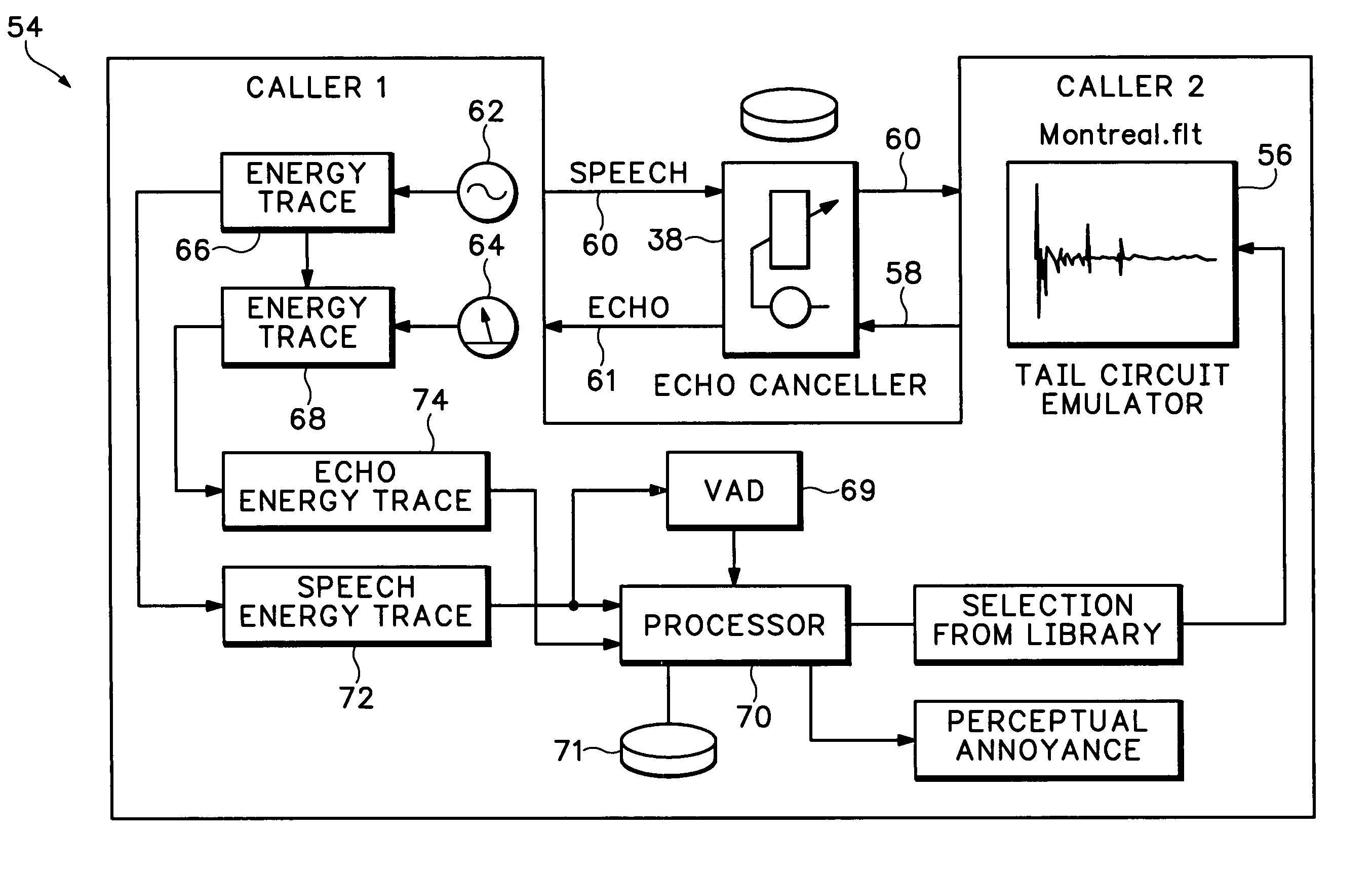
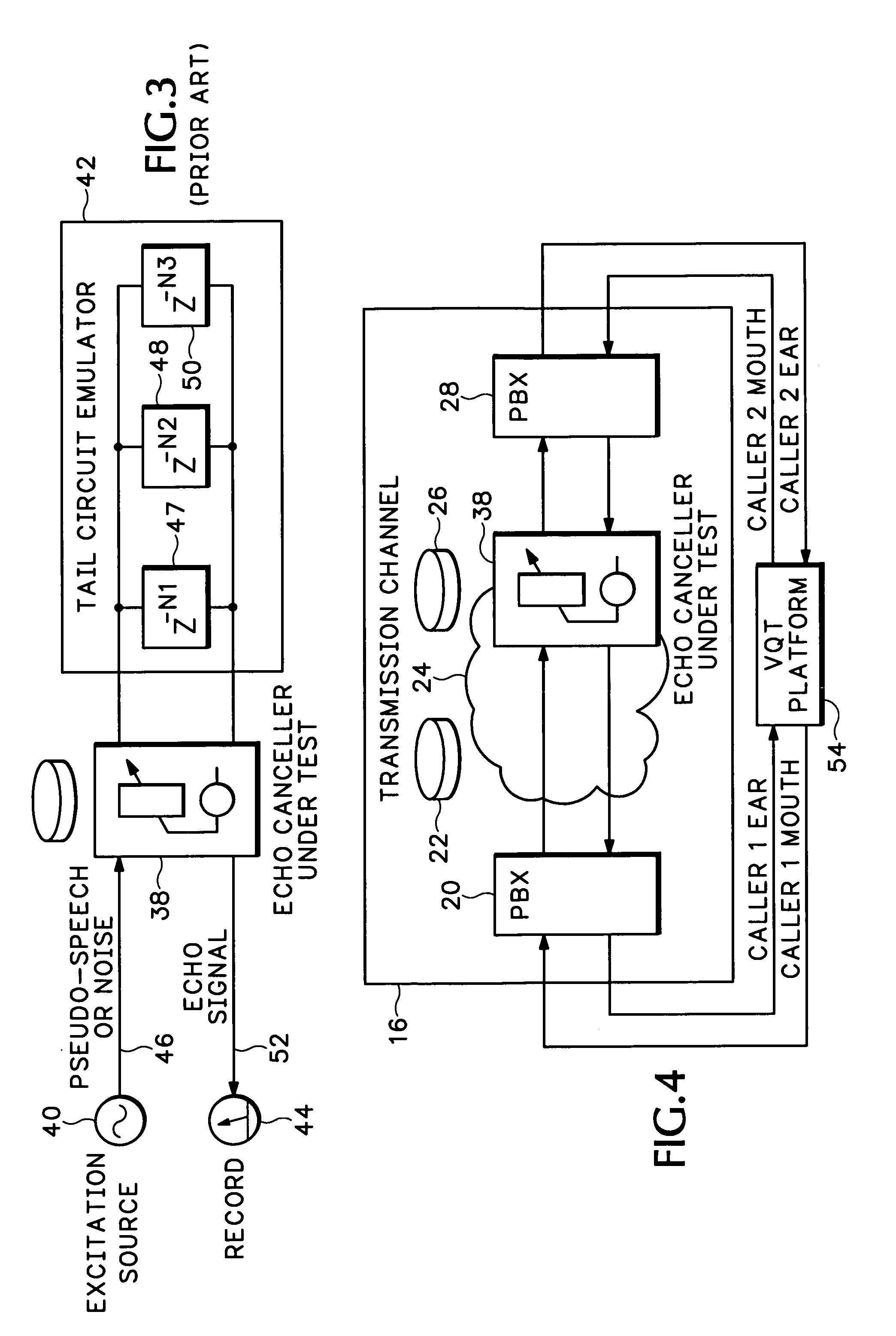
[0028]FIG. 4. is a schematic of a Voice Quality Test (VQT) platform 54 used for testing an echo canceller 38. The VQT platform 54, in one embodiment, is a Personal Computer (PC) with additional audio and signal processing hardware that allows telephone calls to be established, and audio signals to be generated and recorded across a network. The echo canceller 38 under test is located inside the transmission channel 16 between PBX 20 and PBX 28. The VQT platform 54 is connected to the transmission network via a 4-wire interface that may be Ear and Mouth (E&M), T1 / E1, or packet-based (Ethernet). FIG. 4 shows an Ear and Mouth interface. The VQT platform 54 originates and terminates a call between the two telephony interfaces of the transmission network under test.

[0029]In FIG. 4, a left side interface of the VQT platform 54 is marked caller 1. The caller 1 interface goes ‘off-hook’ and dials up caller 2 on the right side interface of the VQT platform 54.

[0030]Caller 2 answers the call....


PUM


Abstract

A test system measures performance of telephone network echo cancellers using a primary criterion of estimated user annoyance due to audible returned echo. The invention generates live telephone calls, uses real speech samples as stimulus signals and provides tail-circuit emulation using actual measured telephone tail-circuit impulse responses. These features provide better ‘real-life’ test conditions for the echo canceller system under test than current ITU standard test methods. Two methods are employed for echo canceller performance evaluation via metrics of estimated user annoyance due to echo. Energy-based method employs point-by-point comparison of talker speech and talker echo signal energy envelopes and uses variable energy thresholds for estimation of echo audibility. A perceptual-model based method uses a Perceptual Speech Distortion Metric (PSDM), such as ITU P.861, in an unique configuration to estimate user annoyance due to audible echo. Echo canceller performance is tested under both single-talk and double-talk conditions. Innovative application of the PSDM method in double-talk tests allow estimation of quality of received double-talk speech.

Description

BACKGROUND OF THE INVENTION[0001]The invention relates generally to a system for testing performance of a telephone network echo canceller and more specifically to a test system that rates echo canceller performance according to user perceptual annoyance.[0002]FIG. 1 is a schematic of a packet-based telephone system 12. A telephone 14 is coupled through a transmission channel 16 to a tail circuit 18. The transmission channel 16 includes a Public Branch Exchange (PBX) 20 that couples the telephone 14 to a voice packet gateway 22 in a packet-switched network 24. Another voice packet gateway 26 at another location in the packet-switched network 24 is connected through a PBX 28 to a telephone 30 in the tail circuit 18.[0003]The telephone 14 is in a first location, such as San Jose, and the telephone 30 is in a second location, such as Montreal. A user of telephone 14 in San Jose may experience an echo problem when connected to the telephone 30 in Montreal. The echo problem is typically ...

Claims


Application Information

Patent Timeline
Patent Type & Authority Patents(United States)
IPC IPC(8): H04M1/24H04M3/08H04M3/22
CPCH04M3/002H04M3/22H04M3/323
Inventor CONNOR, KEVIN J.KNAPPE, MICHAEL E.JAGADEESAN, RAMANATHAN T.
Owner CISCO TECH INC
Why Eureka
Try Eureka