Tunable optical filters

Inactive Publication Date: 2006-02-14
GILAD PHOTONICS
View PDF26 Cites 8 Cited by
  • Summary
  • Abstract
  • Description
  • Claims
  • Application Information

AI Technical Summary

Benefits of technology

[0008]The present invention seeks to provide an integrated optical filter device that is tunable with a narrow linewidth and fast operation, and that can be configured to perform a number of filtering functions, including pass-through and multi-channel drop functions, as well as redirecting optical radiation of

Problems solved by technology

These optical waveguides are fabricated so that each has a precise difference of length relative to neighboring waveguides, thereby producing a phase delay in the light emerging therefrom.
It is worth noting, however, that the manufacturing tolerances for a multiplicity of curved strip optical waveguides are highly demanding even by the standards of the semiconductor industry and put severe constraints on the choice of materials for such devices and on their physical dimensions.
Semiconductors, such as InP, allow devices on the order of 1 cm, but are difficult to couple with optical fibers.
Thus, these devices are large or complex, and are costly.
Further limitations are that they are not tunable with respect to the selected optical wavelengths, and that they require two AWG stages to produce full add/drop optical filter functionality.
However, except for the addition of tunability and other additional features, the disclosed device still has the other disadvantages of the devices described by Smit.
However, t

Method used


Image

  • Tunable optical filters
  • Tunable optical filters
  • Tunable optical filters

Examples


Example

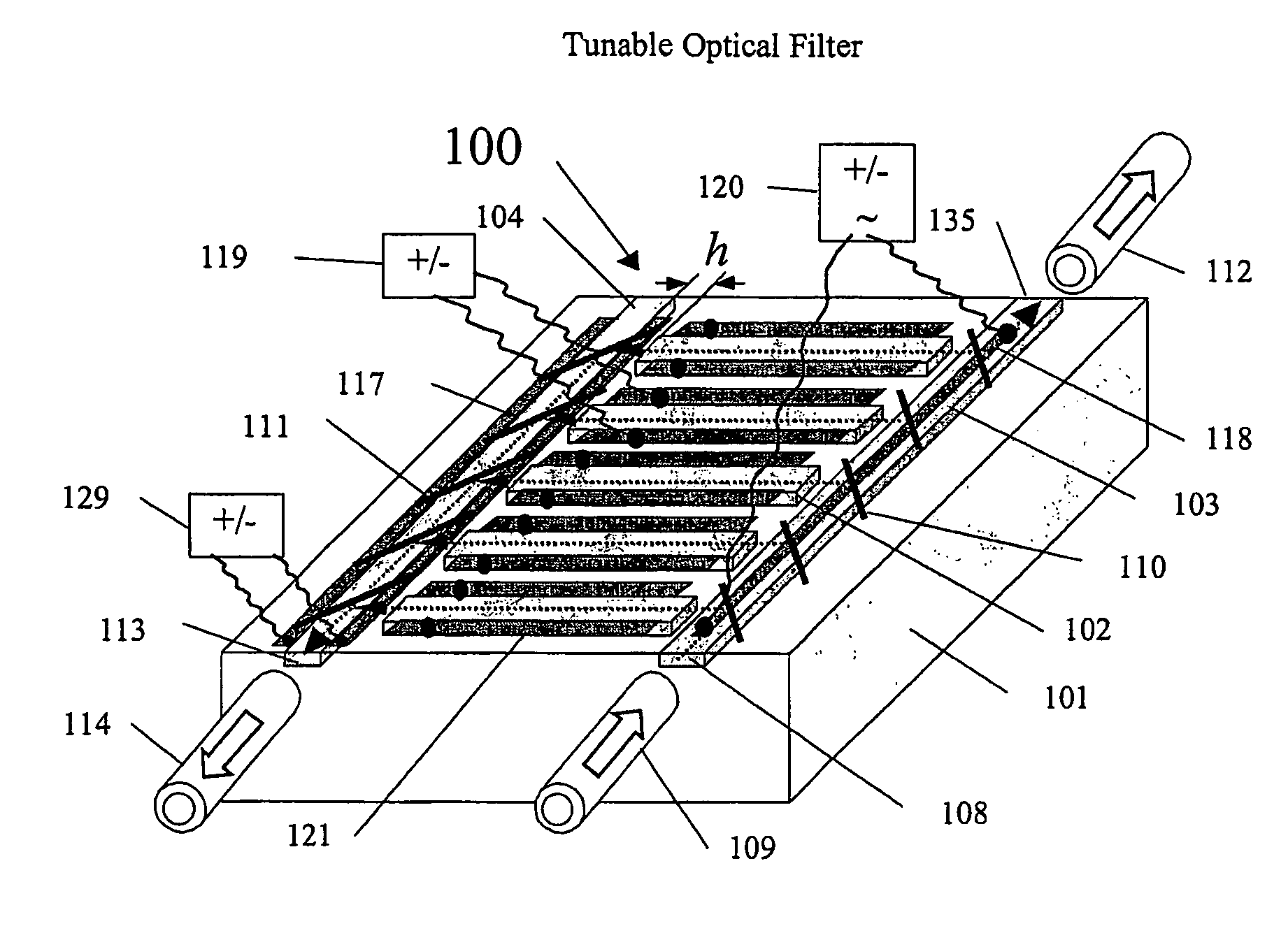
[0032]Referring now to FIG. 1, there is shown a schematic representation of an integrated optical filter device, referred to generally as 100, constructed and operative in accordance with a preferred embodiment of the present invention. Optical filter 100 is fabricated on a surface of a solid-state substrate 101, or alternatively, under it (referred to as the buried waveguide case, which is not shown), of a series of thin strips 102, 103, and 104 of light conducting material having a refractive index greater than that of the adjacent substances, namely, substrate 101 and the air. Such strips will function as strip optical waveguides, so that a narrow and non-divergent light beam can propagate along their length with very low losses (less than 1 dB / cm). Different light propagation modes, which are supported by the waveguide geometry, and their optical fields may be determined by local variation of the refractive index across depth and width of the waveguide structure. Optical filter ...


PUM


Abstract

An integrated optical filter device that is tunable with a narrow linewidth and fast operation, and that can be configured to perform a number of filtering functions, including pass-through and multi-channel drop functions, redirecting optical radiation of different wavelengths into different optical channels. The filter device is easy to fabricate inexpensively and reliably using existing technology and is compact and more densely packed than devices produced by the prior art, even for low refractive index materials, in that it uses substantially straight rather than curved strip optical waveguides. Wavelength tuning can be accomplished by means of a number of alternative control arrangements and configurations.

Description

FIELD OF THE INVENTION[0001]The present invention relates generally to optical devices and, more specifically, to integrated optical filters.BACKGROUND OF THE INVENTION[0002]Modern communication is increasingly based on optical networks. The complexity of emerging networks required in internet applications, for example, with tens, if not hundreds, of channels, demands integrated optical devices produced on materials such as silicon using tools and techniques from the semiconductor industry, as opposed to devices fabricated from discrete optical components. This is demonstrated by Meint K. Smit in his article, “Advanced components for WDM,” ECOC'99, 26–30 September, Nice, France, v. I, pp. 98–99, included herein by reference. In this article, Smit presents Arrayed Waveguide Gratings (AWGs), also known as Phase Arrays (PHASARs) or Waveguide Grating Routers (WGRs), whose purpose is to perform filtering of a selected wavelength of an optical spectrum. In these devices, light is directed...

Claims


Application Information

Patent Timeline
IPC IPC(8): G02F1/035G02B6/12G02B6/34
CPCG02B6/12007G02B2006/12164G02B6/12009
Inventor TSAREV, ANDREI VLADIMIROVICH
Owner GILAD PHOTONICS
Why Eureka
Try Eureka