Controlling the maximum rotation speed of a disk drive device based on the presence of an external power source and the possibility of a buffer underrun

a disk drive and maximum rotation speed technology, applied in the direction of maintaining head carrier alignment, liquid/fluent solid measurement, disk drive circuits, etc., can solve the problems of limited attempts to increase the speed of the disk drive device, increased power consumption in substantially all circuits, and limited data processing circuits, etc., to achieve high-speed data transfer and increase data transfer rate

Inactive Publication Date: 2006-02-14
SANYO ELECTRIC CO LTD
View PDF5 Cites 17 Cited by
  • Summary
  • Abstract
  • Description
  • Claims
  • Application Information

AI Technical Summary

Benefits of technology

[0013]The present invention was conceived in view of the above-described problems of the related art and aims to provide a disk drive device capable of achieving both high speed data transfer and suppressed power consumption when an external power source is not used, in a case where power supply from the interface is insufficient for an increased data transfer rate.
[0014]According to the present invention, in a case where, in data recording onto a disk, the rotation speed of the disk corresponds to a data transfer rate at which power supply from the interface is insufficient, when the external power source is disconnected, the rotation speed of the disk is switched to the maximum speed corresponding to the data transfer rate for which the power supplied through the interface is sufficient for the data processing, thereby avoiding a power shortage situation.

Problems solved by technology

Consequently, when the data transfer rate is increased, power consumption in substantially all circuits, including a disk servo circuit, a data processing circuit, a laser drive circuit, and a head servo circuit of an optical head, also increases.
Accordingly, there is a problem that under current conditions, even for a disk drive device compatible with USB 2.0, sufficient power cannot be supplied to the drive device through the USB interface, and thus attempts to increase the speed of the disk drive device are restricted by the power supply ability of the USB interface.
In other words, high speed disk drive devices can only be achieved when power is supplied from an external power source.
However, it is also necessary to consider the possibility that use of an external power source may not be appropriate in situations where power supply from the external power source is not possible or where use of a cable for connection to the external power source is undesirable, such as when the cable would be unsightly or on obstruction.

Method used


Image

  • Controlling the maximum rotation speed of a disk drive device based on the presence of an external power source and the possibility of a buffer underrun
  • Controlling the maximum rotation speed of a disk drive device based on the presence of an external power source and the possibility of a buffer underrun
  • Controlling the maximum rotation speed of a disk drive device based on the presence of an external power source and the possibility of a buffer underrun

Examples


Embodiment Construction

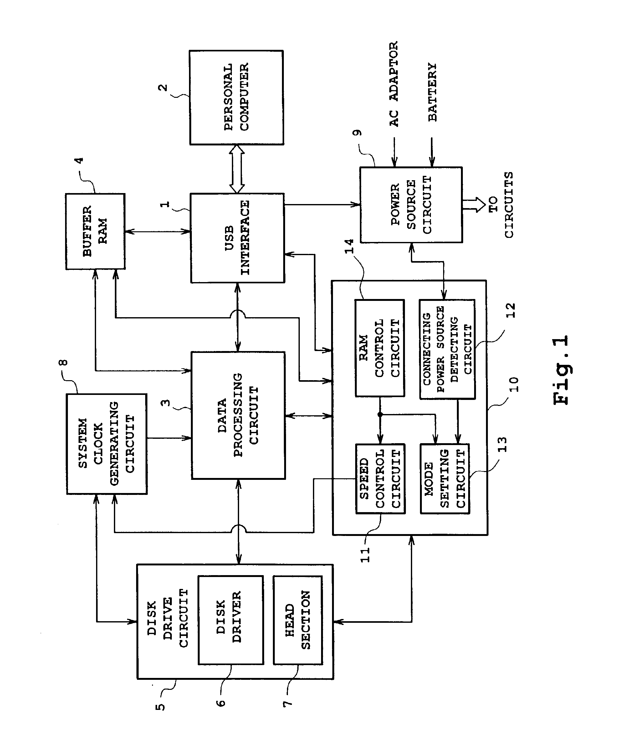
[0021]FIG. 1 illustrates a structure of a disk drive device according to one embodiment of the present invention.

[0022]Referring to FIG. 1, a USB interface 1 controls data reception and transmission to and from a personal computer 2 which serves as a host device. A data processing circuit 3 encodes data supplied from the personal computer 2 to create recording data in the form suitable for recording onto a disk. The data processing circuit 3 also decodes the recording data which is read from the disk. Data input and output through the interface 1 is stored in the buffer RAM 4 which is also used in data processing by means of the data processing circuit 3. A disk drive section 5 includes a disk driver 6 for driving a disk and a head section 7 for driving and controlling an optical head which performs data write and read to and from the disk. An operation clock corresponding to the data transfer rate is supplied by a system clock generation circuit 8 to each circuit. Power is supplied...


PUM

PropertyMeasurementUnit
rotation speedaaaaaaaaaa
speedaaaaaaaaaa
current rotation speedaaaaaaaaaa

Abstract

At the time of data recording onto a disk, when an external power source connection detecting circuit (12) detects that connection of an external power source is released, the currently set rotation speed is recognized. When the current rotation speed cannot be achieved in a maximum speed restricting mode, the processing speed is switched to the maximum speed that can be achieved in the maximum speed restricting mode. At the time of data reproduction on a disk, when the external power source connection detecting circuit (12) detects that the connecting power source is switched to the external power source, the processing speed is automatically switched to the maximum disk rotation speed regardless of the maximum speed restricting mode.

Description

BACKGROUND OF THE INVENTION[0001]1. Field of the Invention[0002]The present invention relates to a disk drive device to which power can be supplied from an interface and an external power source, and relates, for example, to a disk drive device suitable for a device with a USB (Universal Serial Bus) interface.[0003]2. Description of Related Art[0004]CD-R (Recordable) drives and CD-RW (Rewritable) drives of the CD family, which are disk drive devices capable of recording, have been widely introduced as removable storage devices for a personal computers.[0005]In these disk drive devices, attempts have been made to increase the rotation speed of a disk. For recording, CD-Rs are currently capable of high speed recording at 16 or more times the standard speed, and CD-RWs are capable of high speed recording at 8 or 10 times the standard speed.[0006]The USB (Universal Serial Bus) standard is a known interface standard for connecting peripherals to a personal computer. USB interfaces are pr...

Claims


Application Information

Patent Timeline
Patent Type & Authority Patents(United States)
IPC IPC(8): G06F1/32G06F3/06G11B19/00G11B19/28G11B20/10G11B31/00
CPCG11B19/28
Inventor TSUKIHASHI, AKIRA
Owner SANYO ELECTRIC CO LTD
Why Eureka
Try Eureka