Method for scan testing and clocking dynamic domino circuits in VLSI systems using level sensitive latches and edge triggered flip flops

a dynamic domino circuit and scan testing technology, applied in the direction of generating/distributing signals, digital transmission, instruments, etc., can solve the problems of no longer realizing the common performance drawbacks of conventional scan testing of clocked storage elements, and achieve the effect of ensuring the speed and efficiency of data storag

Inactive Publication Date: 2006-02-14
ORACLE INT CORP
View PDF4 Cites 20 Cited by
  • Summary
  • Abstract
  • Description
  • Claims
  • Application Information

AI Technical Summary

Benefits of technology

[0014]The above-described approach enables use of edge triggered flip-flops and level sensitive latches driven from a common single wire clock to perform scan testing thereon without impacting the speed and efficiency of storing data in a dynamic clocked storage element of a VL

Problems solved by technology

Consequently, the inherent performance drawbacks commonly associated with the

Method used


Image

  • Method for scan testing and clocking dynamic domino circuits in VLSI systems using level sensitive latches and edge triggered flip flops
  • Method for scan testing and clocking dynamic domino circuits in VLSI systems using level sensitive latches and edge triggered flip flops
  • Method for scan testing and clocking dynamic domino circuits in VLSI systems using level sensitive latches and edge triggered flip flops

Examples


Embodiment Construction

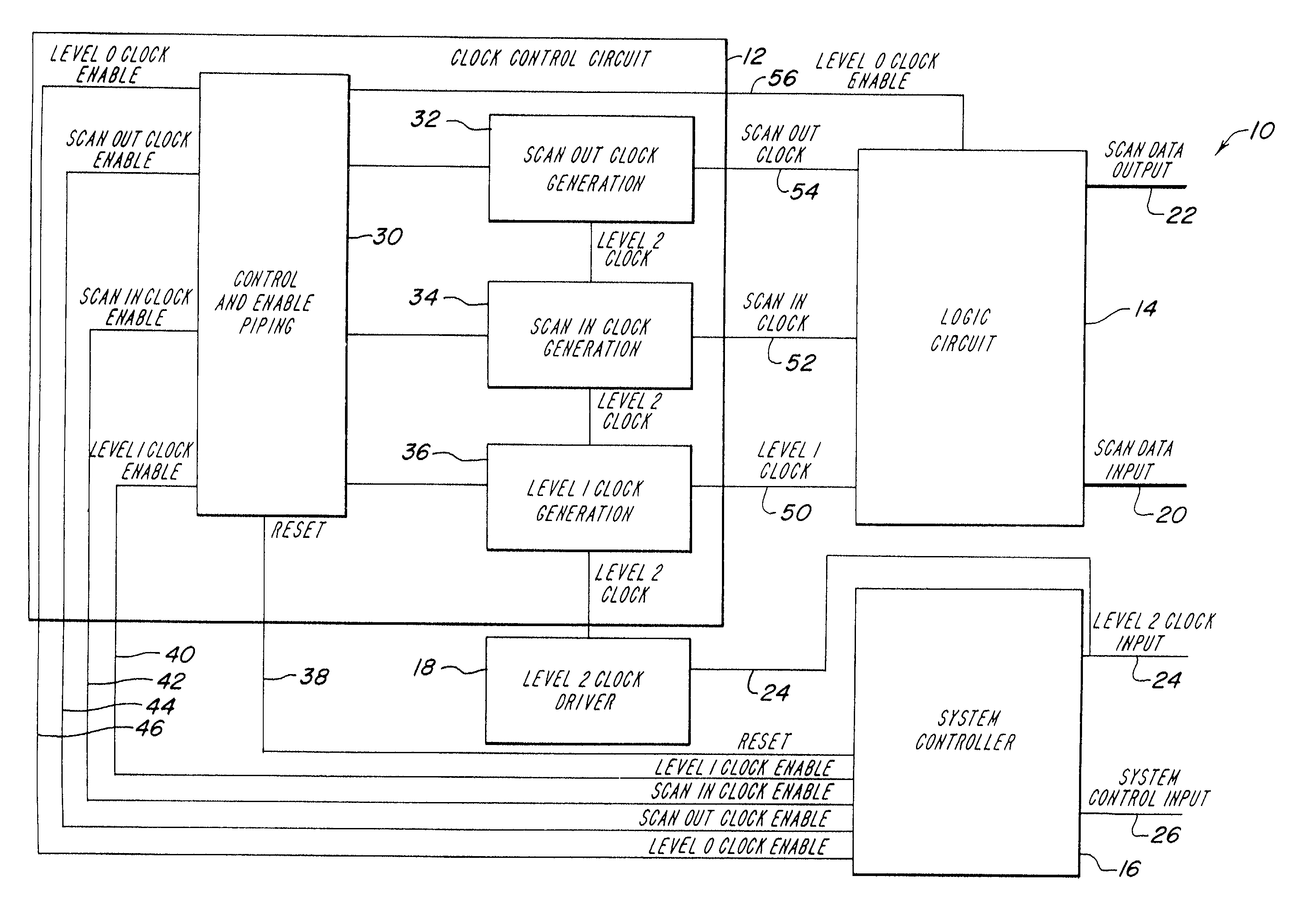
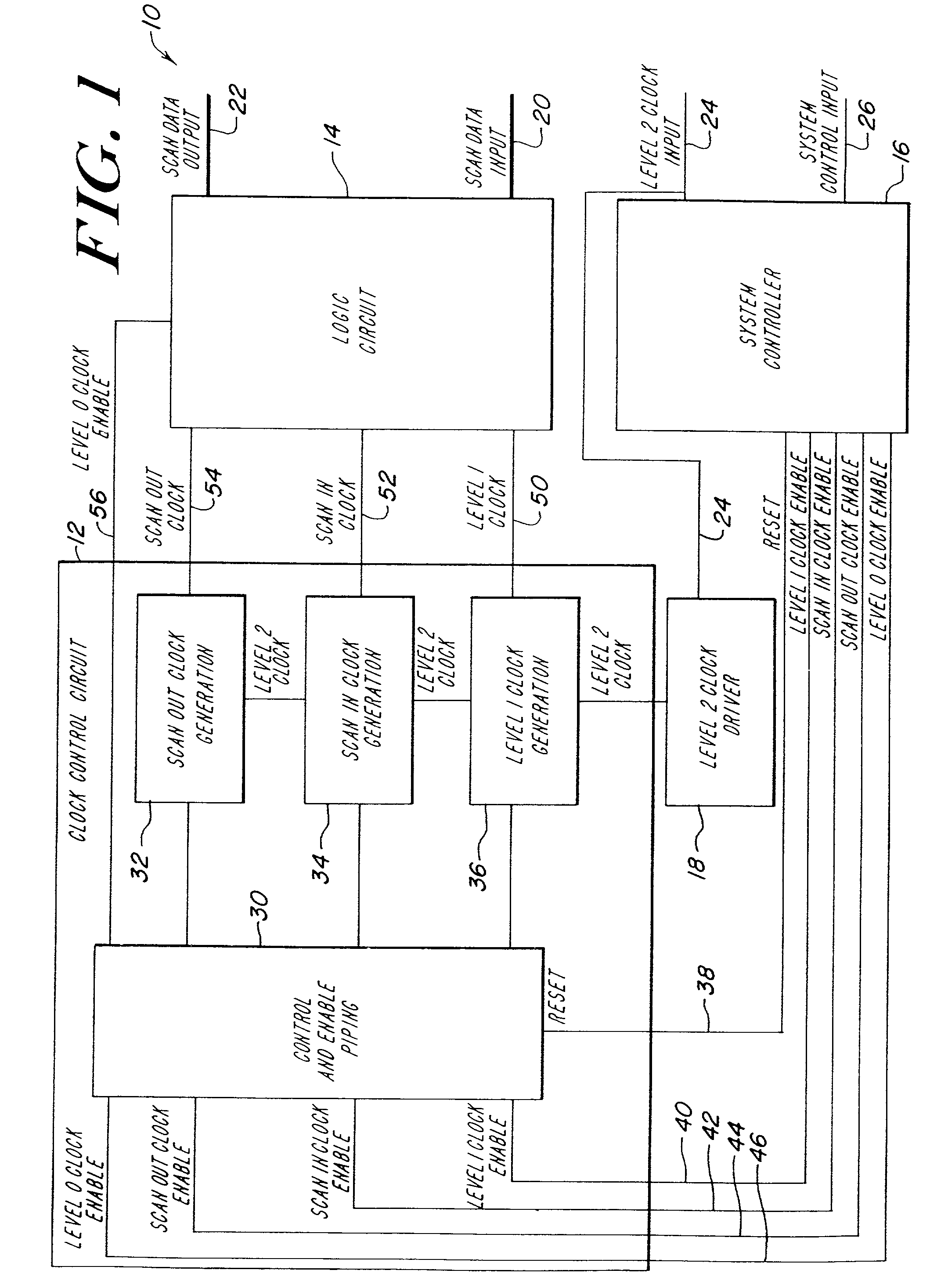
[0028]The illustrative embodiment of the present invention provides a system for performing scan control and observation on any type of clocked storage element without halting the system clock. In the illustrative embodiment, the clock control circuit is adapted to generate the clocks necessary to shift scan data into and out of a scannable logic element and to generate the clock necessary for the scannable logic element to properly operate. Each clock generator of the clock control circuit is coupled to a system controller that provides the control signals to initiate and halt generation of the various clocks. In addition, each clock generator is coupled to the system clock to synchronize clock generation in each clock generator. Hereinafter, the system clock is referred to as the level 2 clock. Nevertheless, those skilled in the art will appreciate that the level 2 clock is a low skew single wire two phase clock distributed throughout the system of the illustrative embodiment of t...


PUM


Abstract

A system and method is provided for scan control and observation of a logical circuit that does not halt the operation of the system clock. Thus, all dynamic circuits within the system continue to evaluate and precharge normally. Moreover, the traditional method of placing a multiplexer before the data input of a clocked storage element to perform scan control and observation is no longer required. Consequently, the system and method provide a more efficient manner in which to perform scan control and observation of a logical circuit.

Description

TECHNICAL FIELD OF THE INVENTION[0001]The present invention generally relates to an integrated electronic system, and more particularly, to clock signal generation for operation of the integrated electronic system.BACKGROUND OF THE INVENTION[0002]The clocked storage element, a level sensitive latch or an edge triggered flip-flop, are used to partition nearly every pipeline stage of a modem microprocessor. Clocked storage elements are utilized in this manner because they hold the current state of a pipeline stage and prevent the next state from entering the pipeline stage until scheduled to do so. Consequently, the clocked storage element synchronizes events between concurrent logic elements with different operational delays. As such, the design of a clocked storage element is tightly coupled to the clocking strategy and circuit topology of the system architecture.[0003]In synchronous sequential circuits, switching events in various stages of the pipeline take place concurrently in r...

Claims


Application Information

Patent Timeline
IPC IPC(8): G01R31/28H04L7/00G01R31/3185
CPCG01R31/318594G01R31/318552
Inventor SIEGEL, JOSEPH R.GREENHILL, DAVID J.WONG, BAN-PAK
Owner ORACLE INT CORP
Why Eureka
Try Eureka