Flow measurement system with reduced noise and crosstalk

a flow measurement and crosstalk technology, applied in the field of ultrasonic flow measurement, can solve the problem of substantially higher signal to noise ratio than expected, achieve high power, effectively repolarize the energy received, and enhance the sensitivity to coherent energy.

Inactive Publication Date: 2006-02-21
GE INFRASTRUCTURE SENSING
View PDF47 Cites 57 Cited by
  • Summary
  • Abstract
  • Description
  • Claims
  • Application Information

AI Technical Summary

Benefits of technology

[0007]The present invention achieves one or more of the foregoing objects by providing first and second clamp-on ultrasonic signal transducers externally coupled or attached to a steam or gas conduit, and positioned to launch and receive contrapropagation signals along a path across the flowing fluid. The transducers apply polarized shear wave to the conduit wall to couple energy to or from a region of the wall transmitting a strong signal into the fluid. Further, the transducers are precisely aligned with the axis along the mid plane of the conduit and when acting as a receiver each transducer has an enhanced sensitivity to coherent energy transmitted through the fluid, effectively re-polarizing energy received along the transit path. The transducers are selected to produce a well defined signal of relatively high power, and preferably in a single mode with a short pulse. The transmitted signal travels along a coupling wedge to provide a polarized shear wave that refracts into the conduit wall. The wedge is preferably a low sound speed (e.g., a polymer) wedge that couples a shear wave beam into the pipe wall at a high angle of incidence so that the vertically polarized beam produces multiple internal reflections within the wall, coherently energizing a region of the wall and radiating the transmitted signal into the fluid as a beam directed across the flow. The vertical shear (SV) configuration of the transmitter and receiver effectively discriminates to receive acoustic energy with polarization on the mid plane of the conduit. Thus, the signal crossing through the fluid maintains its polarization plane, i.e. is repolarized to the same waveform, after two mode conversions through shear-longitudinal-shear along its path from pipe to fluid to pipe. The polarization plane of a transverse wave traveling laterally around the pipe wall rotates after zigzagging inside of the curving pipe wall, and is subject to other interfering or canceling effects, so the SV assembly effectively filters out a substantial amount of the crosstalk present as horizontally polarized shear wave energy propagating along the pipe wall from the opposite transducer. This results in a substantially higher signal to noise ratio than expected, even prior to further (electrical) signal processing.
[0008]The transducer assembly may employ a damped crystal of dimensions effective to provide an output that converts to the desired waves in the pipe wall, i.e., to a vertically polarized shear wave signal, typically at a frequency between about 50 kHz and 1 MHz, depending on the acoustic properties of the fluid and the thickness of the pipe wall. To further reduce short circuit energy inside the pipe wall, including types of plate wave and Rayleigh wave, particularly Rayleigh wave that travels effectively along the curved surface, a couplant such as a gel or gel type of high temperature damping material (polymer) is applied between the conduit and a damper (or just the couplant alone may be applied to the conduit) to couple this part of the energy from the pipe and further minimize the noise effectively. The shear wavelength in the pipe wall is advantageously less than the skip distance in the wall when the system relies on coherent reinforcement to energize a region of the wall, as described further below, to launch a strengthened signal in the fluid.
[0010]The transducers may be coupled to the conduit via a plastic wedge to launch a mode-converted shear wave signal into the wall as a skip or zigzag signal reflecting at a steep angle, or may couple via a stainless steel wedge of appropriate geometry to determine its launch angle into the conduit. The launch angle is set so that the shear wave reflects internally in the conduit to energize a region of the pipe wall for some distance along the direction of flow, and the wedge is aligned so that the signal reflecting within the wall is coupled into the flowing fluid coherently over a region extending along its axis as the wall-borne shear wave signal reflects internally in the conduit wall. The enhanced transmission geometry allows enhanced coupling into the low density fluid, and the receiver may be positioned for signal reception at a position that is as much as one or even several pipe diameters along the flow steam to enhance resolution.

Problems solved by technology

This results in a substantially higher signal to noise ratio than expected, even prior to further (electrical) signal processing.

Method used


Image

  • Flow measurement system with reduced noise and crosstalk
  • Flow measurement system with reduced noise and crosstalk
  • Flow measurement system with reduced noise and crosstalk

Examples


Embodiment Construction

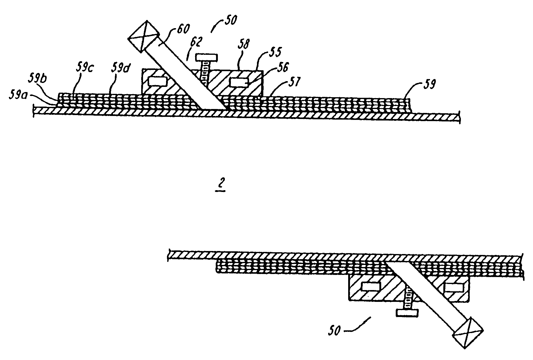
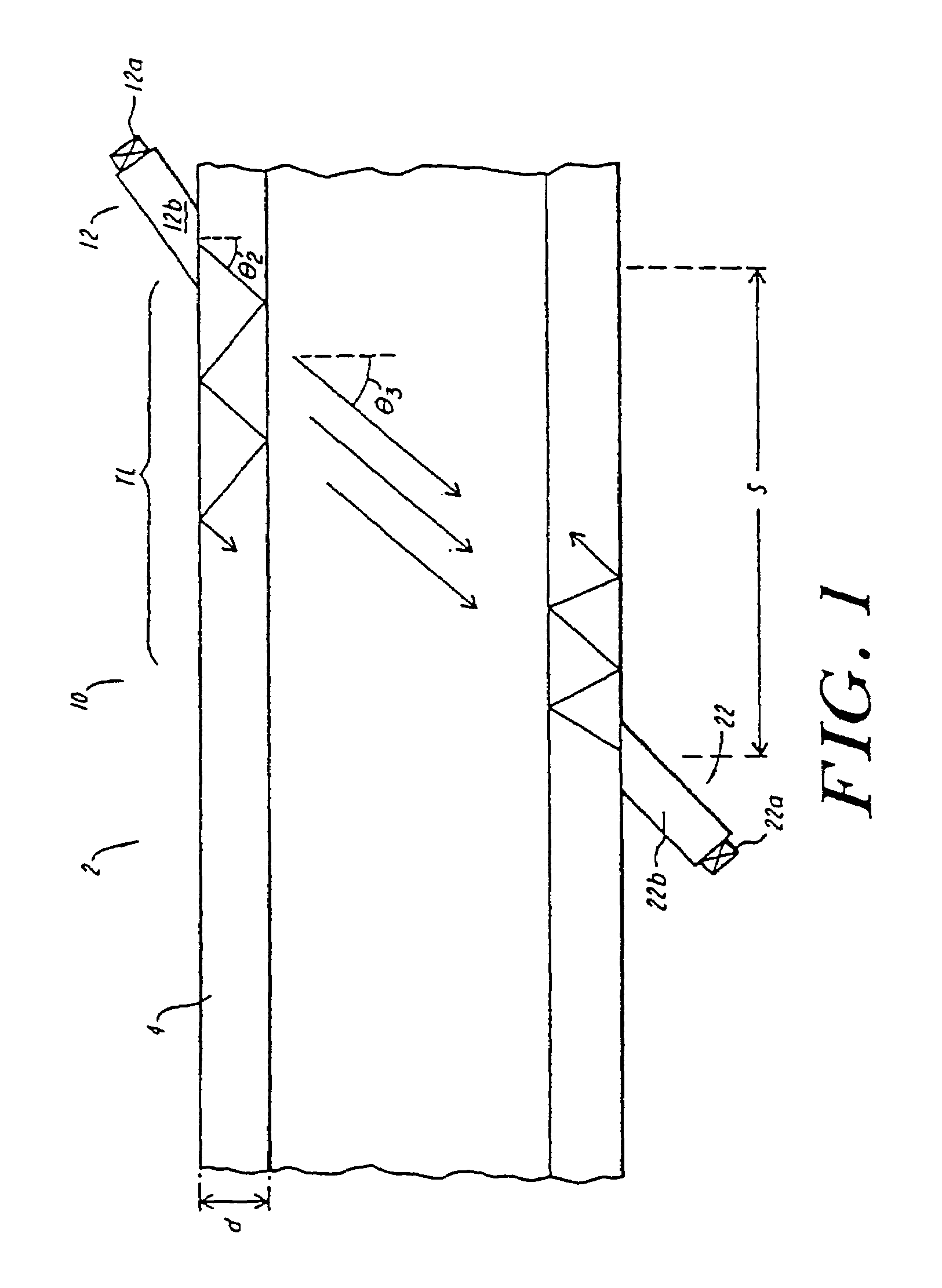
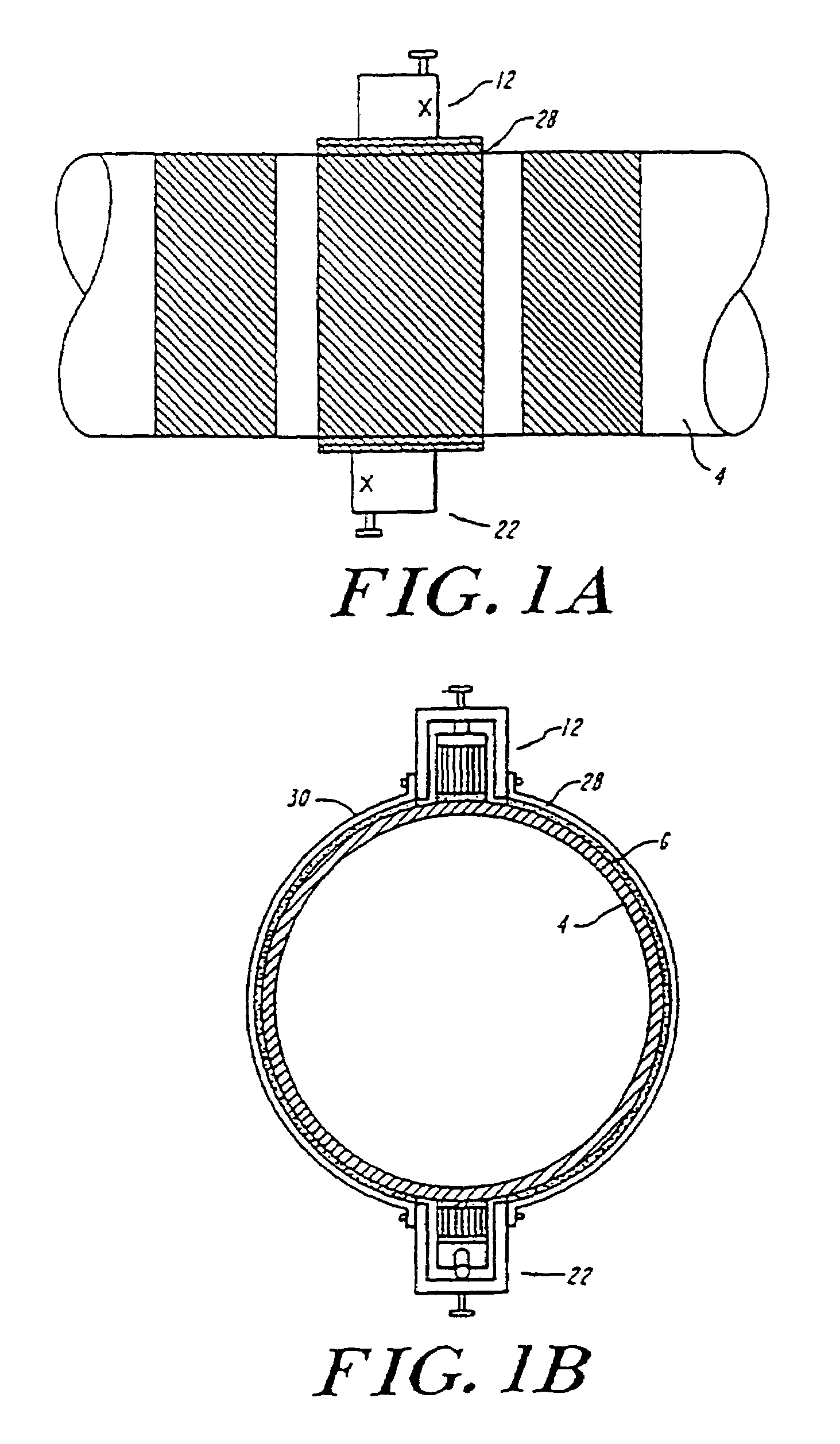
[0021]FIG. 1 shows an exemplary embodiment of a measurement system 10 in accordance with the present invention for measuring the flow of a low density liquid, low pressure steam or a gas such as flare gas in a conduit 2. This material will be referred to below simply as “steam” or “gas”, but will be understood to refer to such fluids generally, and, as applied to steam or gas, to refer both to steam at pressures below about three or four atmospheres up to pressures of fifteen to fifty or more atmospheres, and to a gas which may be at low or ambient pressure such that it presents a substantial impedance mismatch to the stack or conduit in which it flows.

[0022]As shown, the conduit 2 has a wall 4 with a thickness “d” which may, for example, be on the order of one half centimeter to several centimeters or more. As noted above, a problem in measuring a flowing gas or fluid such as steam at low pressure or temperature is that the conduit itself may be quite noisy, and may ring for a long...


PUM


Abstract

A flow measurement system including at least first and second ultrasonic transducers coupled to an existing conduit, a damping material about the conduit between the first and second ultrasonic transducers to prevent crosstalk, a damping material about the conduit upstream of the first ultrasonic transducer to attenuate system background noise travelling in the conduit at large, and a damping material about the conduit downstream of the second ultrasonic transducer to attenuate system background noise travelling in the conduit at large.

Description

RELATED APPLICATIONS[0001]This application is a continuation of U.S. patent application Ser. No. 09 / 539,976 filed Mar. 31, 2000 now U.S. Pat. No. 6,626,049 entitled “CLAMP-ON FLOW METER SYSTEM”, which claims the benefit of U.S. Provisional Patent Application Ser. No. 60 / 127,353 filed Apr. 1, 1999, and this continuation application hereby claims priority to and hereby incorporates herein by reference U.S. patent application Ser. No. 09 / 539,976 and U.S. patent application Ser. No. 60 / 127,353.FIELD OF THE INVENTION[0002]The present invention is related to flow measurement, and in particular to ultrasonic flow measurement wherein a fluid flowing in a conduit is measured by transmitting ultrasonic waves into or across the flowing stream. Such measurement systems are widely used in process control and other situations where fluid measurement is required. In general the constraints involved in setting up any such system involve generating a well defined ultrasonic signal, coupling it into ...

Claims


Application Information

Patent Timeline
Patent Type & Authority Patents(United States)
IPC IPC(8): G01F1/66
CPCG01F1/667G01F1/662
Inventor AO, XIAOLEIBRADSHAW, JAMES E.
Owner GE INFRASTRUCTURE SENSING
Why Eureka
Try Eureka