
Self-attaching female fastener element, sealed fastener and panel assembly and method of forming same

a female fastener and female technology, applied in the direction of threaded fasteners, fastening means, screws, etc., can solve the problems of insufficient torque resistance of pierce nuts formed by cold heading, generally not suitable for thin metal panels, and generally not suitable for anti-rotation means. , to achieve the effect of improving torque resistance and pushing off strength

Inactive Publication Date: 2006-02-21
PENN AUTOMOTIVE INC
View PDF48 Cites 44 Cited by
  • Summary
  • Abstract
  • Description
  • Claims
  • Application Information

AI Technical Summary

Benefits of technology

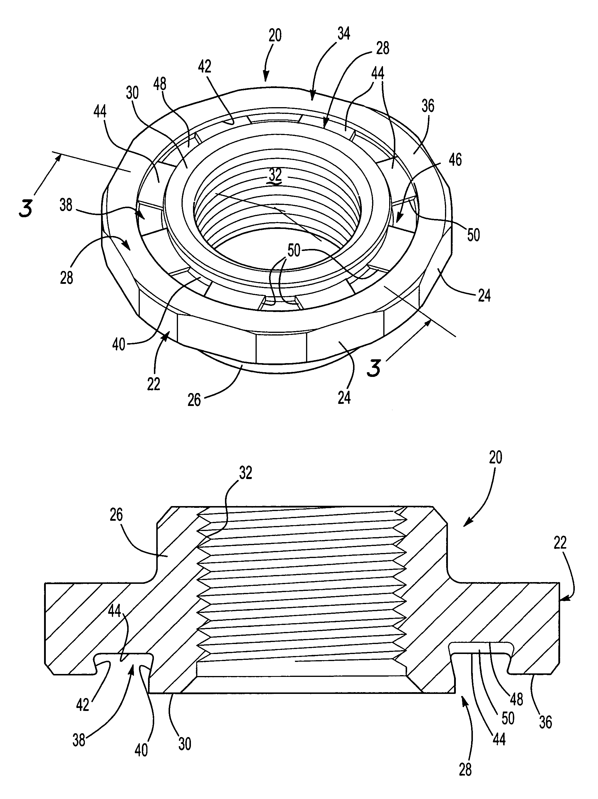
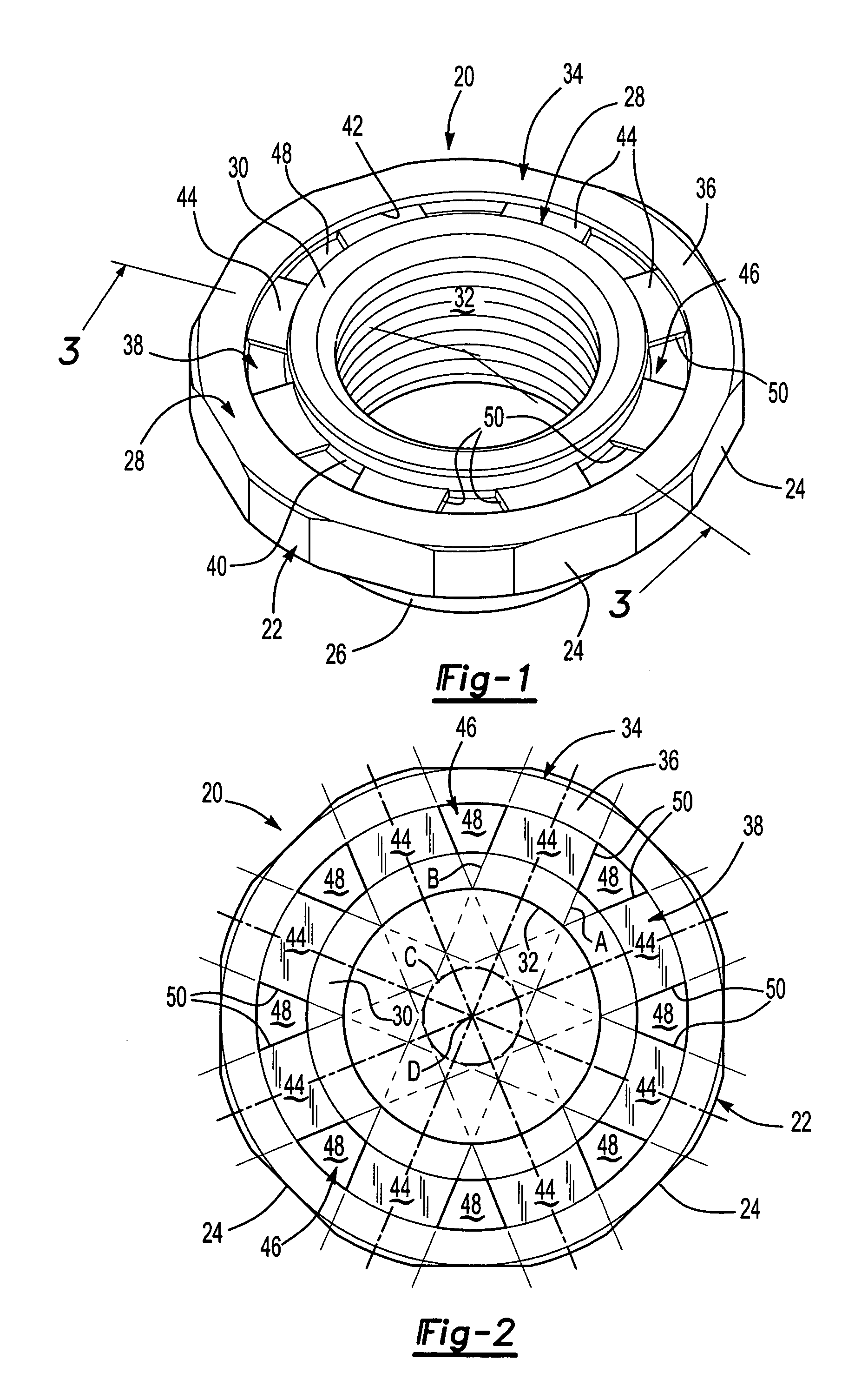
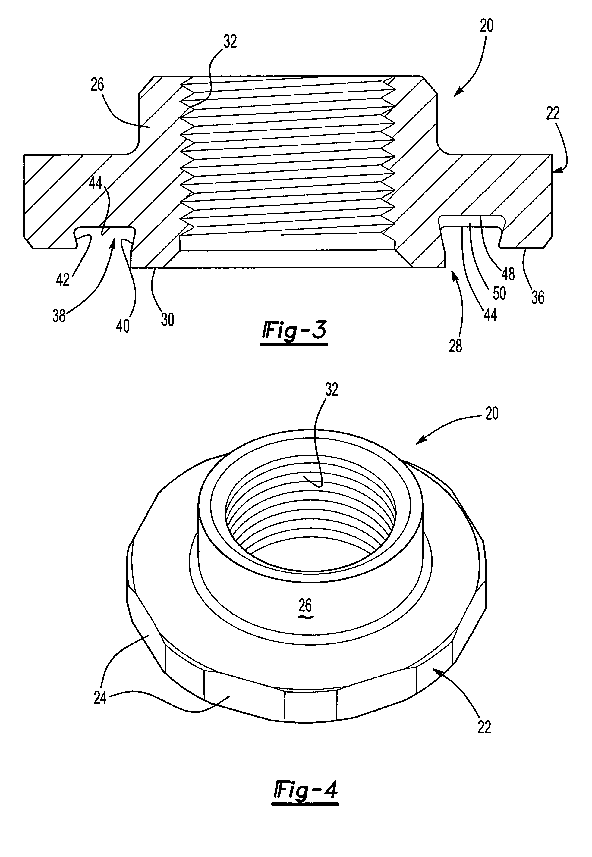
[0006]As set forth above, the self-attaching female fastener element of this invention may be utilized as a self-piercing female fastener to form a sealed joint between the female fastener and a metal panel for applications requiring a sealed joint including, for example, an oil pan nut or bung for a container of liquid. The self-attaching female fastener element of this invention may also be formed by cold header techniques, but provides improved retention of the female fastener element in a panel and sufficient torque resistance in a panel, particularly including relatively thin metal panels such as used by the automotive and appliance industries. The general configuration of the self-attaching female fastener of this invention includes an annular central pilot portion having a bore extending through an annular end face of the pilot portion, an annular flange portion surrounding the pilot portion having a generally planar annular bearing face which is preferably parallel to, but spaced below the plane of the end face of the pilot portion. Where the self-attaching female fastener element of this invention is used as a pierce nut, the end face of the pilot portion is also planar. The self-attaching female fastener element also includes an annular groove in the bearing face of the flange portion surrounding the pilot portion including an annular groove bottom wall, a groove inner side wall adjacent the pilot portion and an outer groove wall inclined from the annular groove bottom wall toward the pilot portion defining a restricted opening to the annular groove adjacent the bearing face of the flange portion. In a preferred embodiment, the groove inner side wall is also inclined from the groove bottom wall toward the flange portion providing improved push-off strength for the fastener and panel assembly.
[0008]The method of attaching a female fastener element to a panel of this invention, wherein the female fastener element is utilized as a self-piercing female fastener or pierce nut, includes driving the planar end face of the pilot portion against a metal panel, thereby piercing an opening through the metal panel and receiving the pilot portion through the panel opening, then driving an annular portion of the panel surrounding the opening against the annular groove bottom wall and against the recess bottom walls, deforming the panel portion radially beneath the inclined inner and outer side walls of the annular groove and against the recess bottom walls, wherein the panel portion is received beneath the inclined inner and outer groove side walls and against the recess side walls forming a secure installation. In a preferred method of attaching a self-piercing female fastener element to a panel, wherein the joint formed between the female fastener element and the panel is sealed, the method further includes deforming an outer portion of the end face of the pilot portion radially outwardly and axially against the annular panel portion received in the annular groove, sealing the assembly. In the disclosed embodiment, the female fastener element is attached to a panel with a die member or die button having an annular lip and a cylindrical opening which receives the slug pierced from the panel. In the disclosed method of assembly, the cylindrical opening through the die button has an internal diameter less than the external diameter of the pilot portion, such that an annular external portion of the pilot portion is deformed radially and axially forming an annular bead which is deformed against the panel portion in the annular groove, entrapping and compacting the annular portion of the panel in the groove, thereby sealing the assembly and providing improved torque resistance and push-off strength.

Problems solved by technology

However, such female fastener elements generally do not form a sealed joint with a metal panel, particularly thin metal panels such as now used by the automotive and appliance industries.
Further, pierce nuts formed by cold heading generally do not have sufficient torque resistance for many applications, such as oil pan nuts.
However, such anti-rotation means are generally not suitable for thin metal panels and the pierce nuts generally do not form a sealed joint.

Method used


Image

  • Self-attaching female fastener element, sealed fastener and panel assembly and method of forming same
  • Self-attaching female fastener element, sealed fastener and panel assembly and method of forming same
  • Self-attaching female fastener element, sealed fastener and panel assembly and method of forming same

Examples


Embodiment Construction

[0015]As set forth above, the self-attaching female fastener element of this invention may be utilized as a self-piercing female fastener or pierce nut wherein the female fastener element pierces an opening in a metal panel and is attached in one stroke of a die press. Alternatively, the self-attaching female fastener may be utilized as a clinch nut, wherein the clinch nut is installed in a prepierced panel opening. The preferred embodiments of the self-attaching female fastener element of this invention may also be formed by conventional cold heading techniques, but provides superior joint integrity, particularly in thin metal applications and may be used to provide a sealed nut and panel assembly by the method of this invention illustrated in FIG. 5 discussed below.

[0016]The embodiment of the self-attaching female fastener element 20 illustrated in FIG. 1, for example, includes a generally cylindrical body 22 having spaced flats 24 and a tubular barrel portion 26 best illustrated ...


PUM

PropertyMeasurementUnit
angleaaaaaaaaaa
circumferential widthaaaaaaaaaa
torque resistanceaaaaaaaaaa

Abstract

A self-attaching female fastener such as a pierce nut having an annular pilot, an annular flange surrounding the pilot and an annular groove in the flange bearing surface surrounding the pilot, wherein the bottom wall of the groove includes wedge-shaped recesses dividing the groove bottom wall into segments having parallel sides defined by the adjacent wedge-shaped recesses and the inclined outer wall of the pilot is deformed radially during installation to entrap and compact panel metal in the groove forming a sealed secure installation having improved push-off and anti-rotation strength.

Description

RELATED APPLICATIONS[0001]This application is a continuation application and claims priority to application Ser. No. 10 / 234,692 filed Sep. 4, 2002, now abandoned.FIELD OF THE INVENTION[0002]The present invention relates to self-attaching female fastener elements, particularly including pierce nuts, sealed fastener and panel assemblies and methods of forming a sealed female fastener and panel assembly.BACKGROUND OF THE INVENTION[0003]There are various types of self-attaching female fastener elements, including pierce nuts, which may be formed by cold heading. However, such female fastener elements generally do not form a sealed joint with a metal panel, particularly thin metal panels such as now used by the automotive and appliance industries. Further, pierce nuts formed by cold heading generally do not have sufficient torque resistance for many applications, such as oil pan nuts.[0004]The prior art includes self-attaching female fasteners formed by cold heading including a central a...

Claims


Application Information

Patent Timeline
Patent Type & Authority Patents(United States)
IPC IPC(8): F16B39/282F16B37/04B21D39/00F16B33/00F16B37/06
CPCF16B33/004F16B37/068F16B37/065
Inventor WOJCIECHOWSKI, STANLEY E.PARKER, JOHN M.
Owner PENN AUTOMOTIVE INC
Learn More