
Optically stimulated luminescence radiation dosimetry method to determine integrated doses and dose rates and a method to extend the upper limit of measureable absorbed radiation doses during irradiation

Inactive Publication Date: 2006-02-21
BOARD OF REGENTS FOR OKLAHOMA STATE UNIVERSITY
View PDF7 Cites 5 Cited by
  • Summary
  • Abstract
  • Description
  • Claims
  • Application Information

AI Technical Summary

Benefits of technology

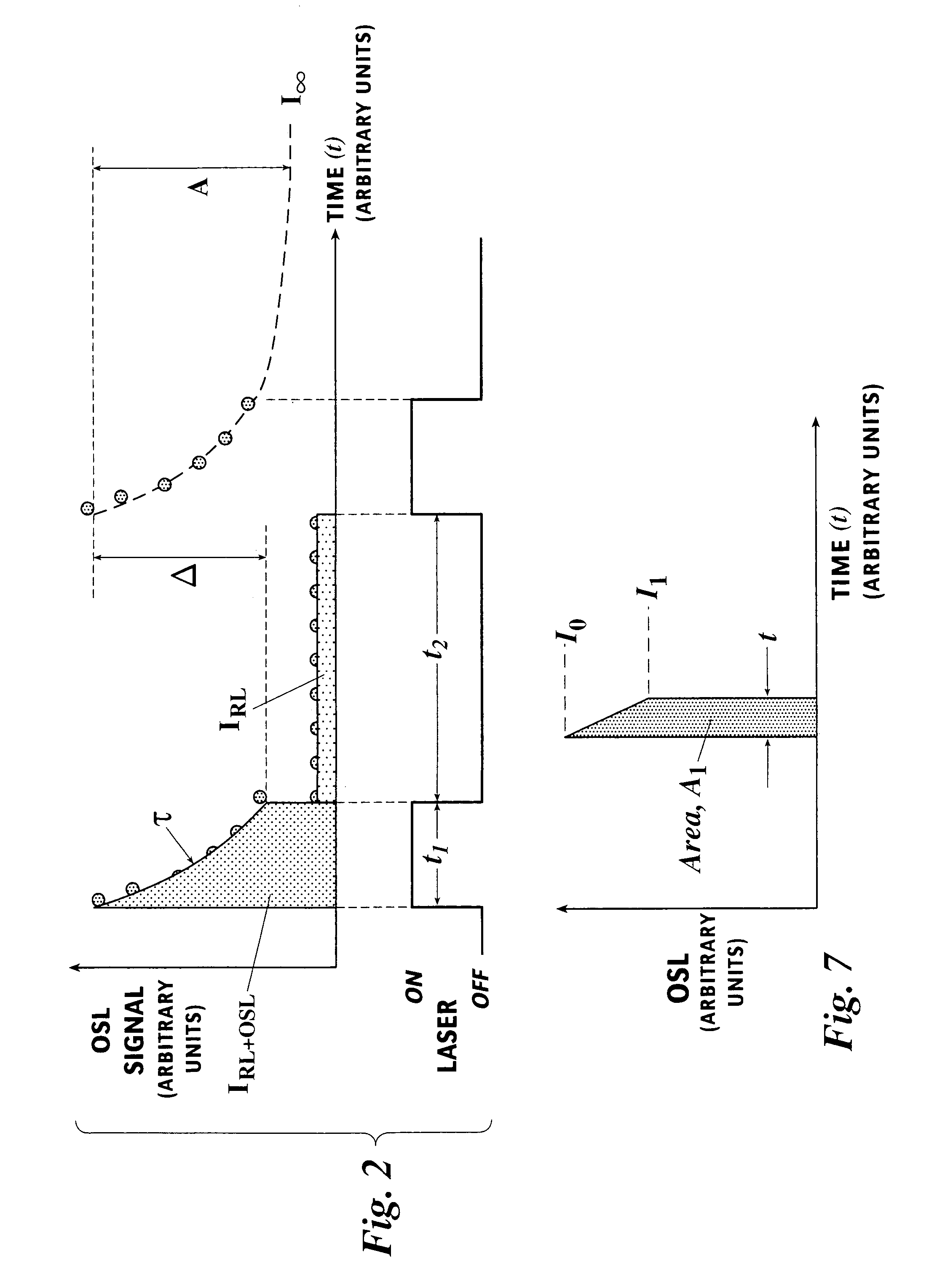
[0009]There is provided herein a system and method for obtaining measurements of radiation exposure in real time using OSL over a wide range of radiation exposures without the restriction of saturation effects.
[0010]In brief, a principal goal of the instant invention is to obtain a signal-versus-dose response from an Optically Stimulated Luminescence (OSL) dosimeter that is linear over all

Problems solved by technology

More particularly, there is a general departure from linearity in the luminescence / dose curve at higher dose levels and it is susceptible to saturation effects.
Further, conventional OSL is not suitable for use in real-time measurement of radiation dose such as would be useful in the treatment of medical disorders by radiation.

Method used


Image

  • Optically stimulated luminescence radiation dosimetry method to determine integrated doses and dose rates and a method to extend the upper limit of measureable absorbed radiation doses during irradiation
  • Optically stimulated luminescence radiation dosimetry method to determine integrated doses and dose rates and a method to extend the upper limit of measureable absorbed radiation doses during irradiation
  • Optically stimulated luminescence radiation dosimetry method to determine integrated doses and dose rates and a method to extend the upper limit of measureable absorbed radiation doses during irradiation

Examples


Embodiment Construction

[0022]Referring now to the drawings, wherein like reference numerals indicate the same parts throughout the several views, there is provided a preferred system and method for determining integrated does and does rates and a method to extend the upper limit of measurable absorbed radiation does during irradiation.

Preferred Apparatus

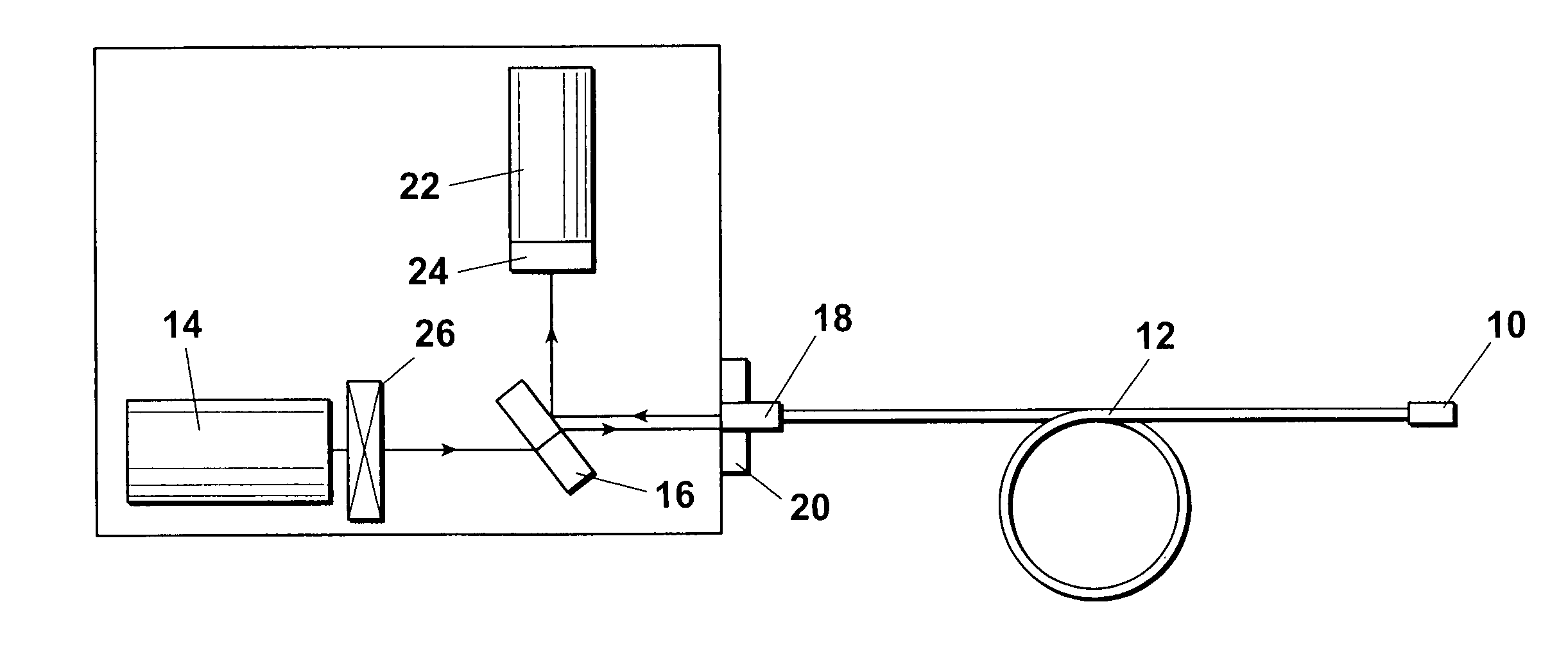
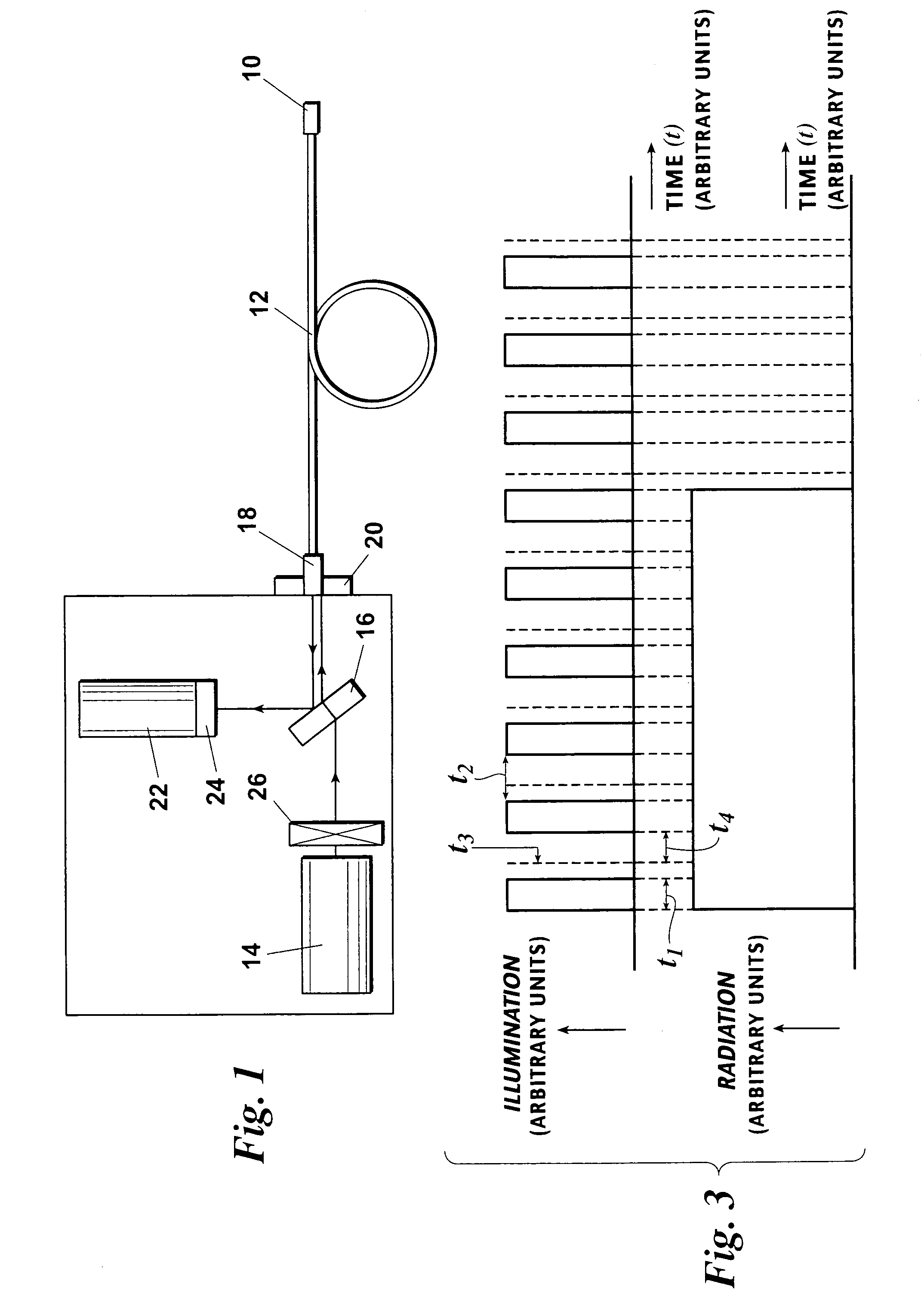
[0023]The equipment and method used for measuring the OSL signal during irradiation is preferably as follows. An Al2O3 single crystal is connected to the end of a fiber optic cable. The crystal is placed inside a radiation field. Preferably, light from a Nd:YAG laser (532 nm) is transmitted down the fiber to stimulate the crystal. Luminescence from the crystal is transmitted back up the fiber and is directed into a photomultiplier tube (PMT). Filters are used to prevent the light from the laser being directly detected by the PMT, which only sees the luminescence from the Al2O3 crystal.

[0024]FIG. 1 contains a preferred hardware arrangement suitable for use ...


PUM


Abstract

There is provided herein a system and method for obtaining measurements of radiation exposure in real time using OSL and for obtaining improved accurate OSL measurements over a greater range of radiation exposures. In a preferred embodiment a signal-versus-dose response is obtained from an OSL dosimeter that is linear over all doses and does not exhibit saturation effects. The desired response is preferably calculated from the measured OSL-versus-time response from a suitable dosimeter obtained during irradiation. To obtain the desired response from the measured OSL data each measured OSL point has to be corrected for the depletion of the trapped electron concentration that occurs during each illumination period.

Description

CROSS REFERENCE TO RELATED APPLICATION[0001]This application claims the benefit of U.S. Provisional Application No. 60 / 473,662, which application was filed with the Patent and Trademark Office on May 23, 2003, which application is hereby incorporated by reference.FIELD OF THE INVENTION[0002]This invention relates generally to methods for using Optically Stimulated Luminescence (OSL) in radiation dosimetry and, more specifically, improved methods for using OSL to determine integrated doses and dose rates over wide dose ranges.BACKGROUND OF THE INVENTION[0003]Luminescence techniques in radiation dosimetry have traditionally been dominated by thermal methods in which a sample (a thermoluminescence dosimeter, or TLD) is exposed of radiation and is then heated in the dark. At a certain temperature, or within a certain temperature range (either of which is dependent upon the material used and the detailed parameters of the heating procedure), luminescence is emitted from the material. The...

Claims


Application Information

Patent Timeline
IPC IPC(8): G01T1/10G01T1/105G02B
CPCG01T1/105
Inventor POLF, JERIMY C.GAZA, RAZVANMCKEEVER, STEPHEN W. S.
Owner BOARD OF REGENTS FOR OKLAHOMA STATE UNIVERSITY
Learn More