

Fixed-frequency beam-steerable leaky-wave microstrip antenna
a microstrip antenna and fixed frequency technology, applied in leaky-waveguide antennas, resonant antennas, radiating element structural forms, etc., can solve the problems of impracticality of trying to scan the same beam at fixed frequency, and achieve the effect of low reverse bias voltage requirements
- Summary
- Abstract
- Description
- Claims
- Application Information
AI Technical Summary
Benefits of technology
Problems solved by technology
Method used
Image

Examples
Embodiment Construction
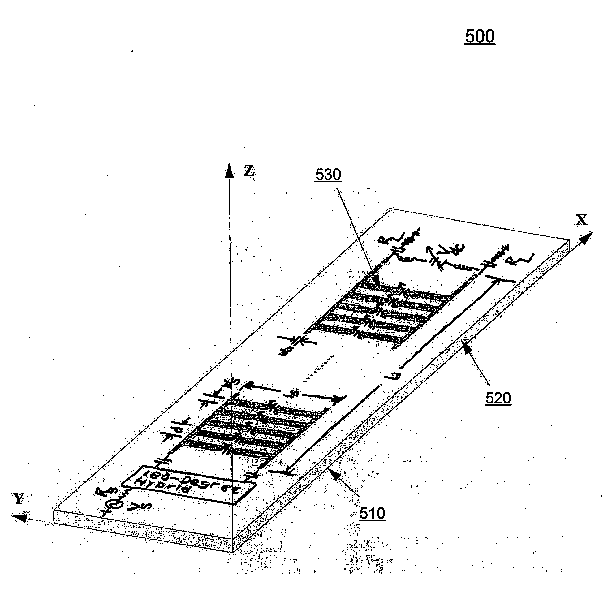
[0032]The present invention discloses an improved fixed frequency continuously beam-steerable leaky-wave antenna in microstrip. The antenna's radiating strips are loaded with identical shunt-mounted variable-reactance elements, resulting in low reverse-bias-voltage requirements. The microstrip antenna is excited in its first higher-order mode by means of two equal-amplitude and 180°-out-of-phase signals. These signals are applied to the feed end of the microstrip conducting traces at two ports. A port is defined herein to consist of two closely spaced terminals across which a signal may be applied. About ninety percent of the input power is radiated by the electromagnetic wave by the time it reaches the terminated antenna end. By varying the reverse-bias voltage across the variable-reactance elements, the main beam of the antenna may be scanned continuously at fixed frequency.
[0033]An angled three dimensional view of a reactively loaded fixed frequency beam steerable leaky wave micr...
PUM
 Abstract
Description
Claims
Application Information