
Noise-reducing blower structure

a blower and noise reduction technology, applied in lighting and heating apparatus, electrical apparatus casings/cabinets/drawers, semiconductor/solid-state device details, etc., can solve the problems of fan vibration, gpu generates a large amount of heat that needs to be removed, and noise level has been cited as an irritation to users, so as to reduce the noise generated by the blower structure, reduce vibration noise, and excellent vibration dampening characteristics

Inactive Publication Date: 2006-02-21
NVIDIA CORP
View PDF7 Cites 56 Cited by
  • Summary
  • Abstract
  • Description
  • Claims
  • Application Information

AI Technical Summary

Benefits of technology

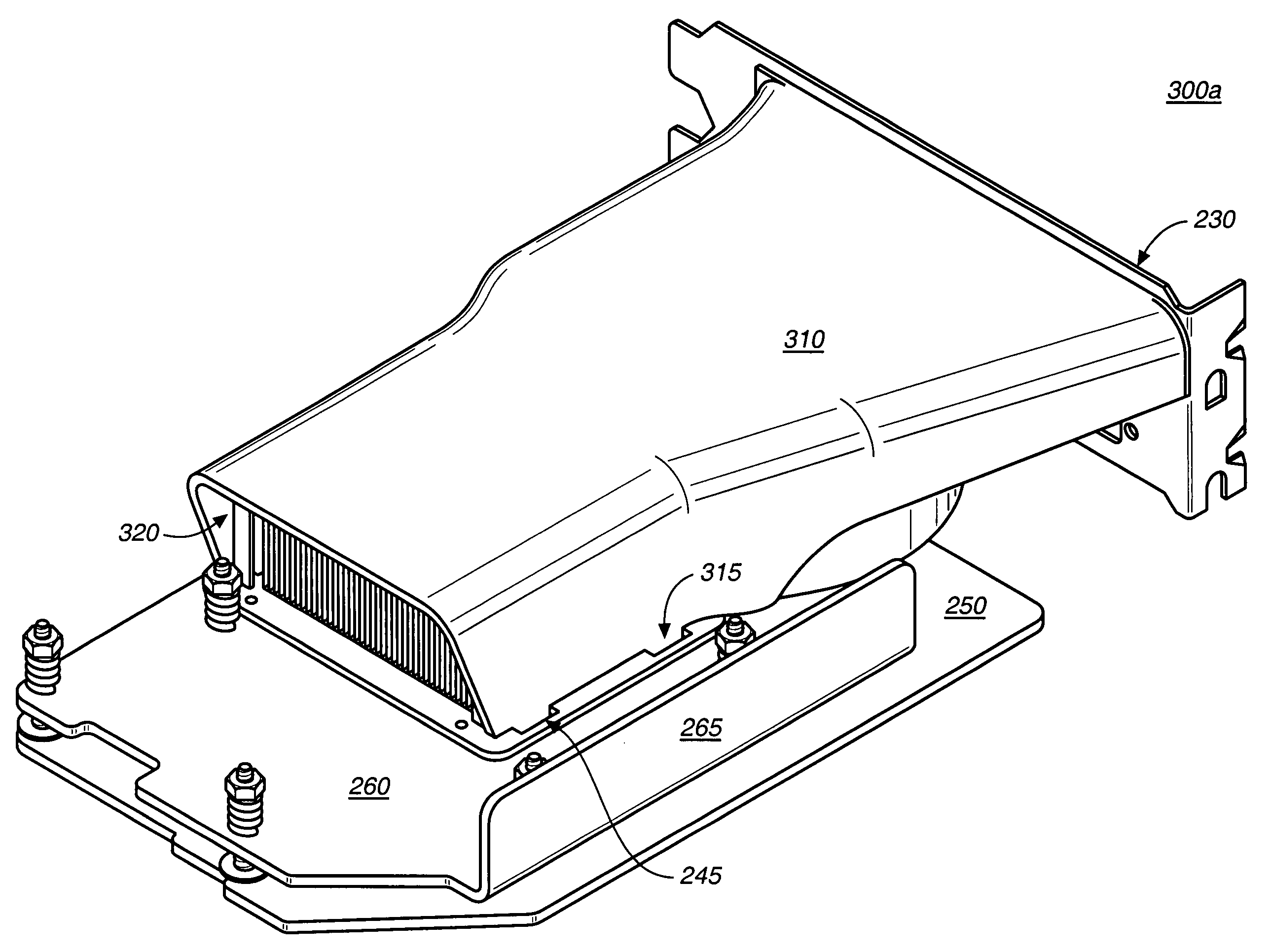
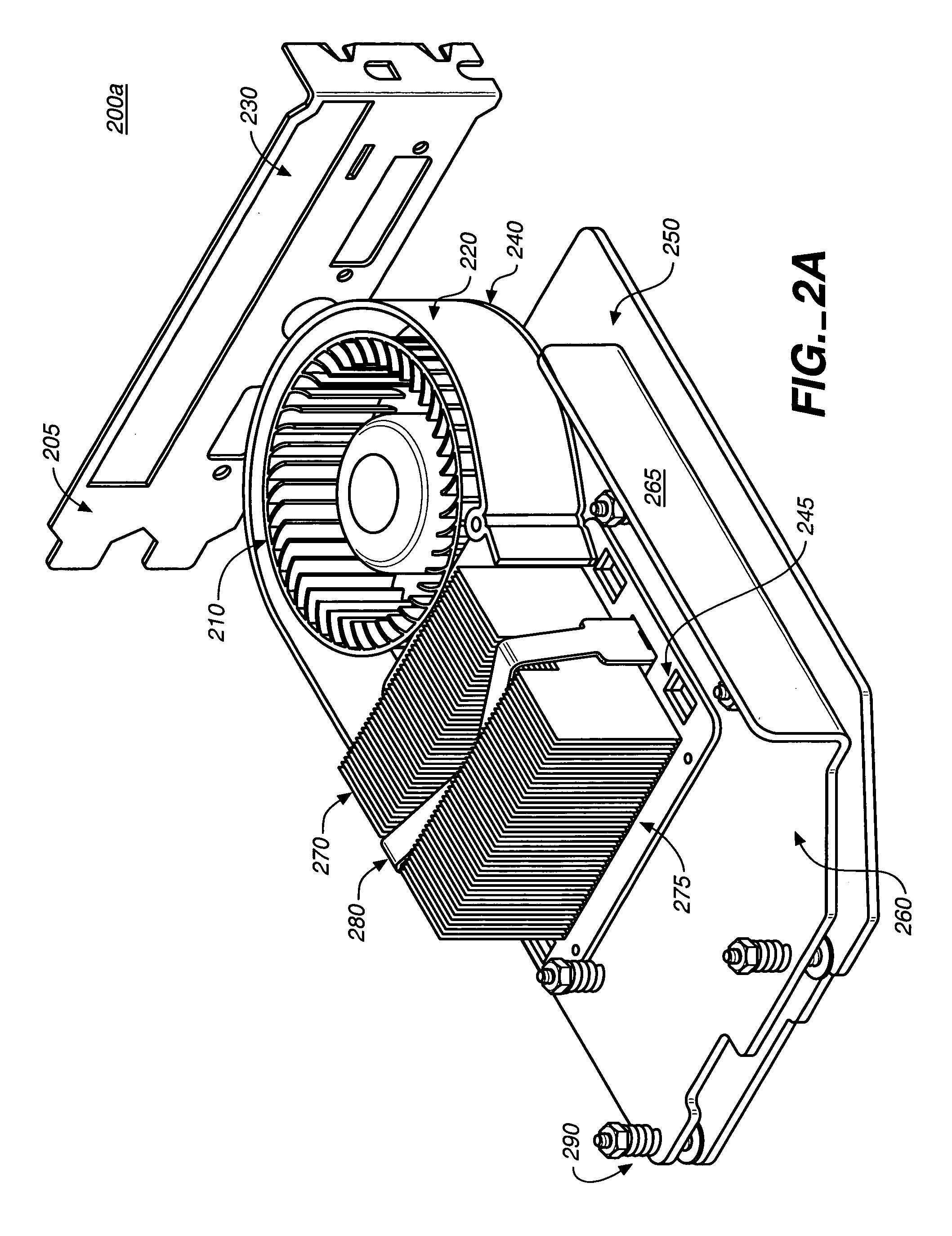
[0009]There is a need for reducing the noise generated by the blower structure in the heat removal system of an expansion card containing a processing unit chip. According to embodiments of the present invention, a noise-reducing blower structure is disclosed in which a fan-housing is coupled to a graphics card (having a graphics processing unit) and juxtaposed to a heat sink. In one embodiment a duct and fan housing are constructed out of a material having excellent vibration dampening characteristics. In addition, the fan housing is mechanically separated from the duct by a dampening space. In one embodiment, the heat sink is coupled to the graphics card and resides within a rigid frame above the graphics processing unit chip. In one embodiment, a fan that circulates air is coupled to the graphics card within the fan-housing. A duct is coupled to the graphics card, in one embodiment, covering the heat sink and the fan-housing, and the duct is separated from the fan-housing for reducing vibration noises.
[0010]Embodiments of the present invention advantageously improve the noise produced by the heat removal system of a GPU card. Embodiments of the present invention are also advantageous in that the frame for the heat sink combined with the relative locations of the GPU chip and the heat sink, increase the structural stiffness of the GPU card at the GPU chip location and reduce the breakage rate of the GPU chip. Embodiments of the present invention are also advantageous in that the design of the GPU heat sink provides a larger surface area for heat dissipation at a location nearest to the GPU chip, thus providing increased heat dissipation where needed.

Problems solved by technology

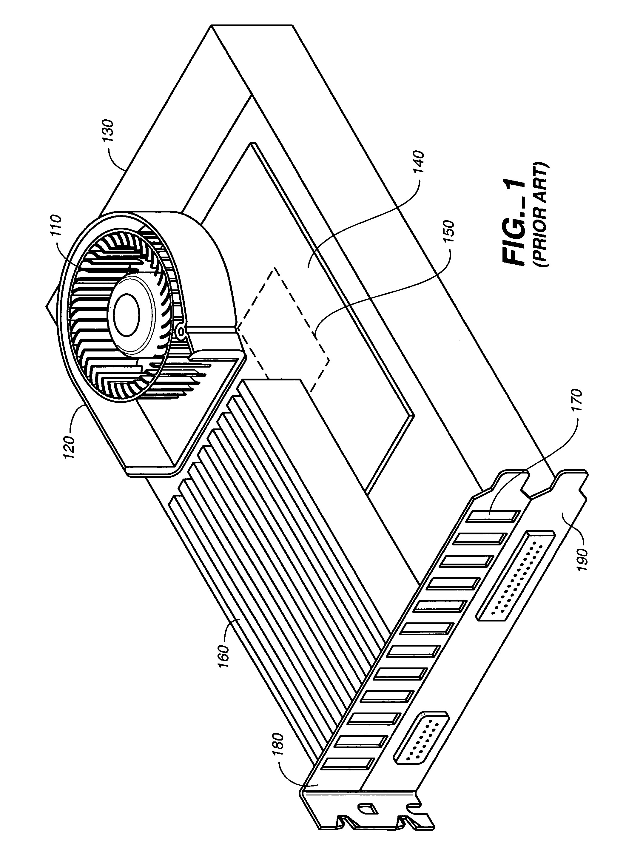
The GPU generates a very large amount of heat that needs to be removed.
Fans typically vibrate due to mass imbalance in their rotors.
This noise level has been cited to be an irritation to users.
The large amount of sound (45 to 50 db), that is observed to be generated when fan 110 runs at high speed, creates an annoyance for many users.
Another problem with the card configuration of FIG. 1 is that having the fan structure mounted on top of the GPU and the heat sink mounted on top of the fan structure creates a thick design.
In addition to the noise produced, there is an additional problem with the GPU card with regard to its flexibility.
The GPU chip is fairly fragile, in that it contains balls that are easily broken away if the chip is flexed.
Both the noise factor and the GPU chip breakage due to flexing of the card present undesirable features of the conventional GPU card.

Method used


Image

  • Noise-reducing blower structure
  • Noise-reducing blower structure
  • Noise-reducing blower structure

Examples


Embodiment Construction

[0020]Reference will now be made in detail to the embodiments of the invention, examples of which are illustrated in the accompanying drawings. While the invention will be described in conjunction with the preferred embodiments, it will be understood that they are not intended to limit the invention to these embodiments. On the contrary, the invention is intended to cover alternatives, modifications and equivalents, which may be included within the spirit and scope of the invention as defined by the appended claims. Furthermore, in the following detailed description of the present invention, numerous specific details are set forth in order to provide a thorough understanding of the present invention. However, it will be obvious to one of ordinary skill in the art that the present invention may be practiced without these specific details. In other instances, well-known methods, procedures, components, and circuits have not been described in detail as not to unnecessarily obscure aspe...


PUM


Abstract

Embodiments of the present invention provide for a noise-reducing blower structure in which a fan-housing is disposed on an expansion card and juxtaposed to a heat sink. The heat sink is disposed on the expansion card and resides within a rigid frame above a processing unit chip. A fan that circulates air is disposed on the expansion card within the fan-housing. A duct is disposed on the expansion card, covering the heat sink and the fan-housing, and the duct is mechanically separated from the fan-housing for reducing vibration noises. By placement of the fan next to the heat sink, and not on top of it, the fan can be made larger to thereby rotate at slower speeds.

Description

[0001]This Application is related to and claims priority from commonly owned and invented provisional U.S. Patent Application No. 60 / 523,134, filed Nov. 17, 2003, by Michael B. Wittig entitled “HEAT-REMOVING BLOWER STRUCTURE WITH IMPROVED ACOUSTICAL CHARACTERISTICS,” and hereby incorporated by reference herein in its entirety.FIELD OF THE INVENTION[0002]Embodiments of the present invention relate to blower structures for cooling components in computer systems, and more particularly to reducing noise produced by the blower structures.BACKGROUND OF THE INVENTION[0003]Many computer systems today are being equipped with expansion cards. Some cards contain a graphics processing unit (GPU) that is used primarily for 3-D applications, creating lighting effects and transforming objects each time a 3D scene is redrawn. The GPU is a single-chip processor that is capable of performing these mathematically intensive tasks and, thus, removing the burden of these calculations from the CPU. The GP...

Claims


Application Information

Patent Timeline
IPC IPC(8): H05K7/20
CPCH05K7/20154
Inventor WITTIG, MICHAEL B.
Owner NVIDIA CORP
Learn More