Small array microphone for acoustic echo cancellation and noise suppression

a microphone and array technology, applied in the field of signal processing, can solve the problems of affecting the sound quality of the system, so as to suppress the residual echo, and reduce the noise of the ambient environment.

Active Publication Date: 2006-02-21
FORTEMEDIA
View PDF11 Cites 391 Cited by
  • Summary
  • Abstract
  • Description
  • Claims
  • Application Information

AI Technical Summary

Benefits of technology

[0016]Techniques are provided herein for canceling echo and suppressing noise using an array microphone and signal processing. These techniques are effective at (1) suppressing residual echo that is not canceled by conventional echo cancellation and post filter techniques, and (2) reducing stationary and non-stationary ambient noise as well as diffused noise, which

Problems solved by technology

However, the microphones may also pick up undesirable reflections of the acoustic signal from the borders of an enclosure, such as a room or a car compartment.
As a result, the electro-acoustic circuit in the system may become unstable and produce howling, which is highly undesirable.
In general, users are annoyed by hearing their own voice delayed, for example, by the path of the system.
However, conventional echo cancellation techniques are not able to remove certain portions of the echo.
This type of echo cannot be canceled by conventional echo cancellation techniques that employ only an adaptive filter.
Moreover, user movement, position changes in the microphones and loudspeakers, and volume changes can cause the echo path to vary.
This results in time-varying echo that typically cannot be canceled very well, particularly if the echo path changes faster than the convergence rate of the adaptive filter.
However, these techniques typically cannot cancel echo due to serious nonlinearity.
These techniques also cannot handle high volume echo.
Moreover, some conventional nonlinear echo cancellation techniques, such as a center clipper, can cause voice distortion by cutting off low power voice signal.
Other conventional

Method used


Image

  • Small array microphone for acoustic echo cancellation and noise suppression
  • Small array microphone for acoustic echo cancellation and noise suppression
  • Small array microphone for acoustic echo cancellation and noise suppression

Examples


Embodiment Construction

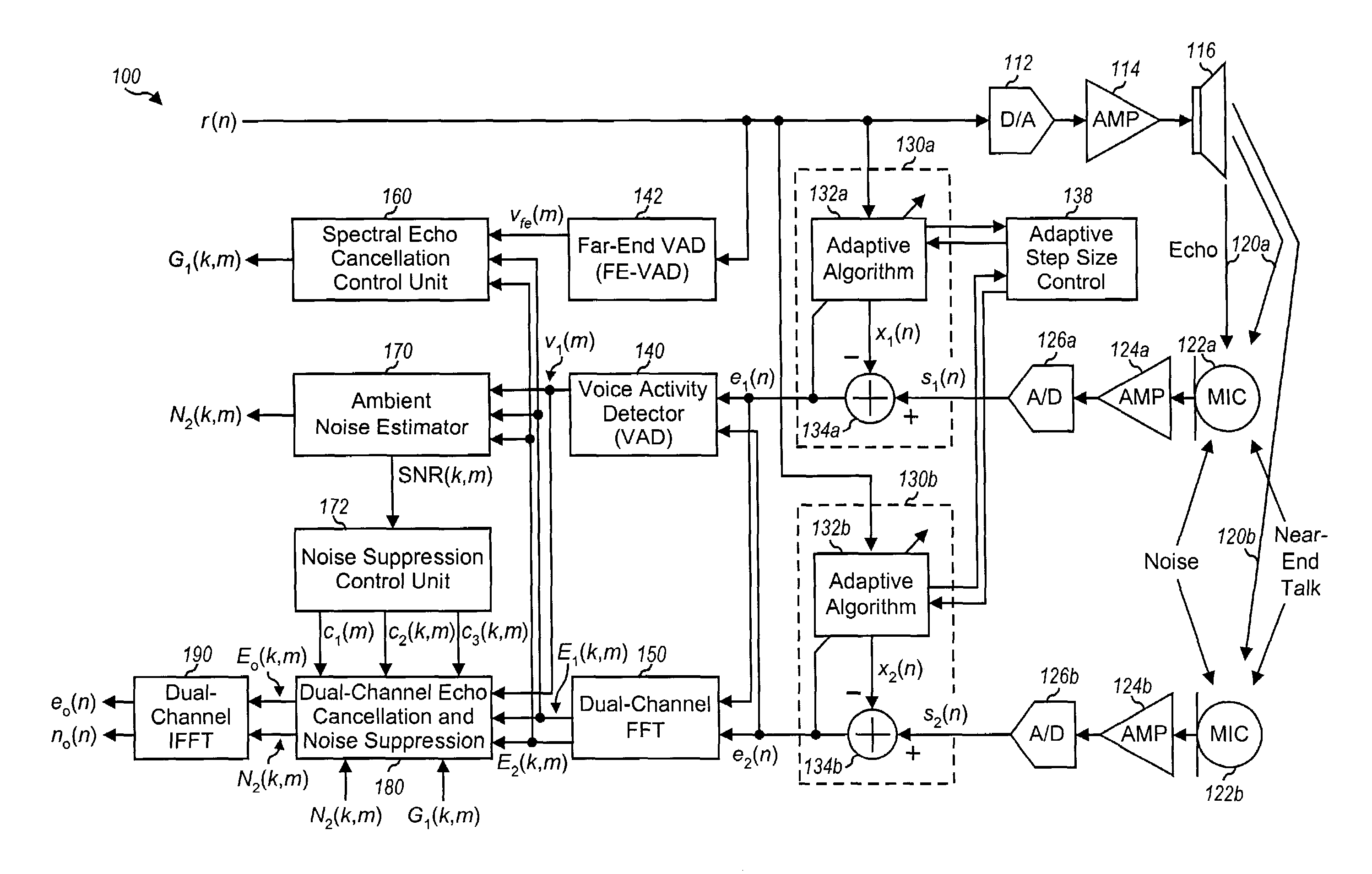
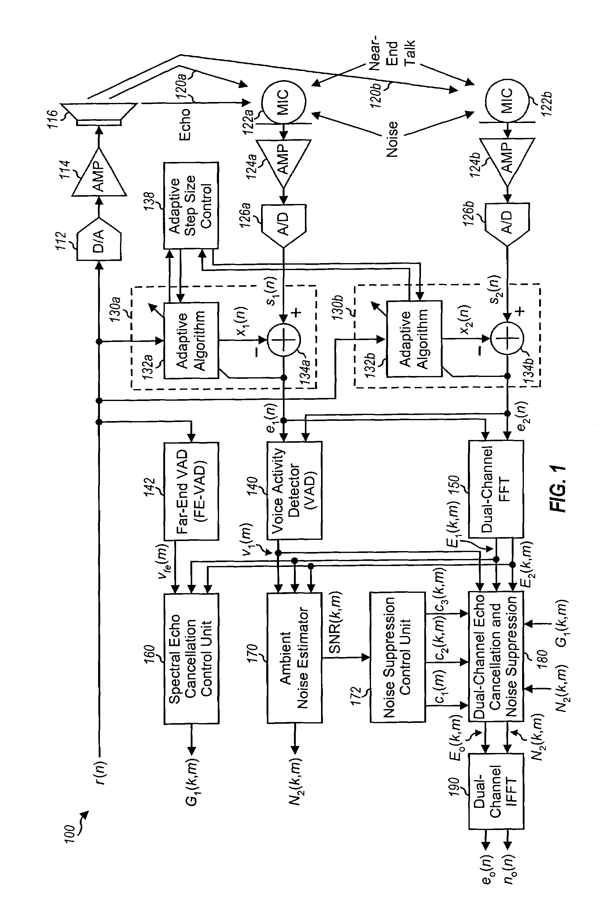
[0031]For clarity, various signals and controls for the acoustic echo cancellation and noise suppression systems described herein are labeled with either lower case or upper case symbols. Time-variant signals and controls are labeled with “(n)” and “(m)”, where n denotes sample time and m denote frame index. Frequency-variant signals and controls are labeled with “(k,m)”, where k denotes frequency bin index. Lower case symbols (e.g., r(n)) are used to denote time-domain signals, and upper case symbols (e.g., E(k,m)) are used to denote frequency-domain signals.

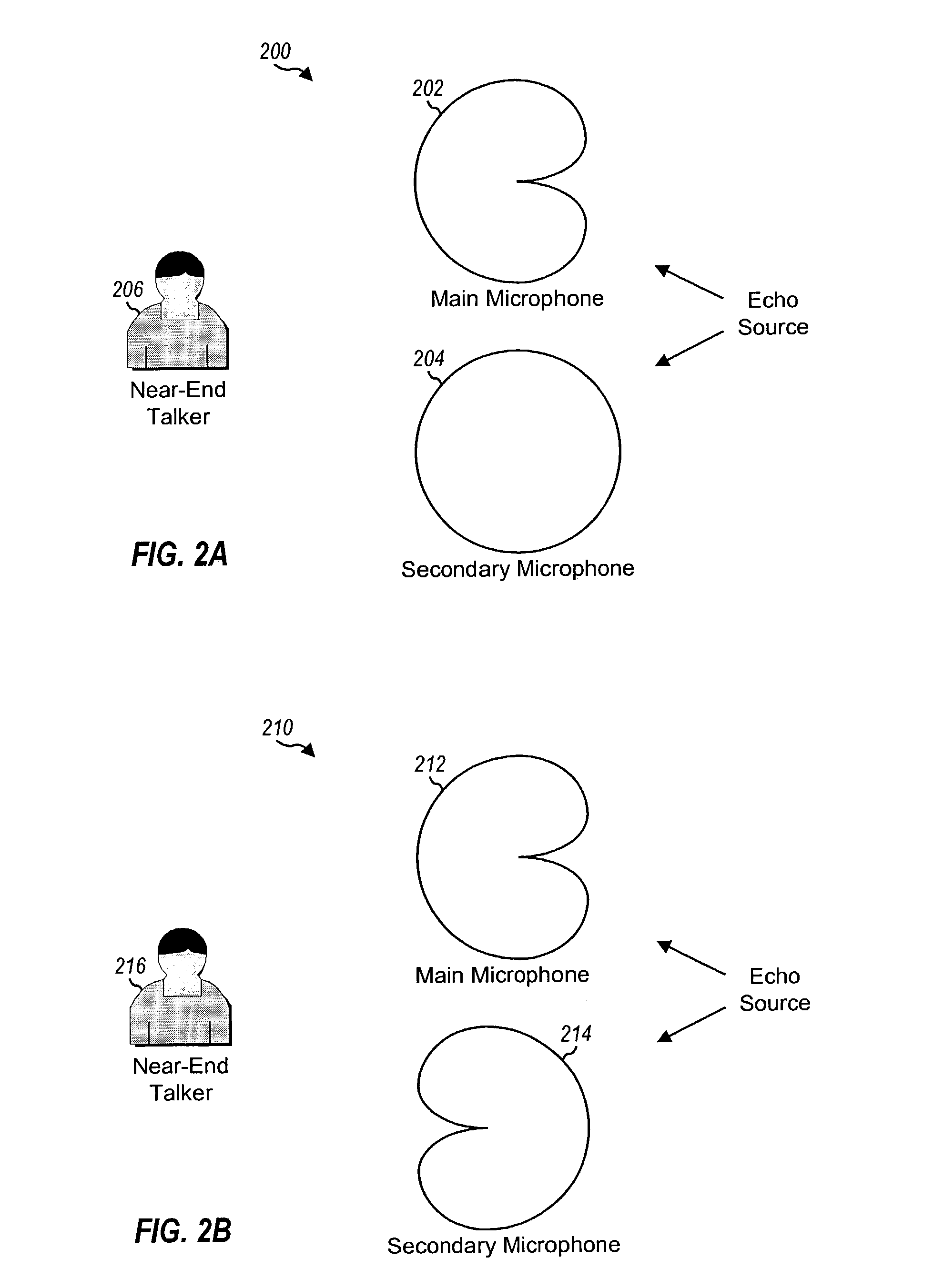
[0032]FIG. 1 shows a block diagram of an echo cancellation and noise suppression system 100, which is a specific embodiment of the invention. For system 100, multiple microphones are placed in a manner to form an array microphone. Various configurations may be used for the array microphone and two exemplary configurations are briefly described for illustration. In a first configuration, the array microphone comprises one uni-di...


PUM


Abstract

Techniques for canceling echo and suppressing noise using an array microphone and signal processing. In one system, at least two microphones form an array microphone and provide at least two microphone input signals. Each input signal may be processed by an echo canceller unit to provide a corresponding intermediate signal having some echo removed. An echo cancellation control unit receives the intermediate signals and derives a first gain used for echo cancellation. A noise suppression control unit provides at least one control signal used for noise suppression based on background noise detected in the intermediate signals. An echo cancellation and noise suppression unit derives a second gain based on the control signal(s), cancels echo in a designated intermediate signal based on the first gain, and suppresses noise in this intermediate signal based on the second gain. The signal processing may be performed in the frequency domain.

Description

CROSS-REFERENCES TO RELATED APPLICATIONS[0001]This application claims the benefit of provisional U.S. Application Ser. No. 60 / 426,661, entitled “Small Array Microphone for Acoustic Echo Cancellation and Noise Suppression,” filed Nov. 15, 2002, which is incorporated herein by reference in its entirety for all purposes.[0002]This application is further related to U.S. application Ser. No. 10 / 193,689, entitled “Channel Control and Post Filter for Acoustic Echo Cancellation,” and U.S. application Ser. No. 10 / 193,739, entitled “Acoustic Echo Cancellation with Adaptive Step Size and Stability Control,” both filed on Jul. 10, 2002, assigned to the assignee of the present application and incorporated herein by reference in their entirety for all purposes.BACKGROUND OF THE INVENTION[0003]The present invention relates generally to signal processing, and more specifically to techniques for canceling acoustic echo and suppressing noise using array microphone.[0004]Full-duplex hands-free communi...

Claims


Application Information

Patent Timeline
IPC IPC(8): H04B3/23H04B15/02
CPCH04M9/082
Inventor ZHANG, MINGPAI, WAN-CHIEH
Owner FORTEMEDIA
Why Eureka
Try Eureka