Axial flow compressor

a compressor and axial flow technology, applied in the direction of machines/engines, supersonic fluid pumps, liquid fuel engines, etc., can solve the problems of affecting severely impairing the efficiency of the tip end of each rotor blade, and degrading the surge property so as to achieve a wide operating range and improve the efficiency of the rotor blade. , the effect of wide rang

Inactive Publication Date: 2006-02-28
HONDA MOTOR CO LTD
View PDF4 Cites 26 Cited by
  • Summary
  • Abstract
  • Description
  • Claims
  • Application Information

AI Technical Summary

Benefits of technology

[0005]In view of such problems of the prior art, a primary object of the present invention is to provide an improved axial flow compressor which can improve the efficiency of the rotor blades over a wide operating range including a partial load range.
[0006]A second object of the present invention is to provide an improved axial flow compressor which can improve the efficiency of the rotor blades without substantially complicating the manufacturing process.
[0008]Thereby, a compressive wave is produced upstream of the shockwave so that the Mach number of the flow entering the shockwave can be reduced. As a result, the shockwave is made less severe, and the shockwave loss can be reduced. In particular, because the concave surface is provided in the casing wall as opposed to the case where the concave surface is provided in the negative pressure side of the rotor blade, the reduction in the performance owing to the change in the angle of the airflow entering the passage defined by the concave surface under a partial load condition can be avoided.
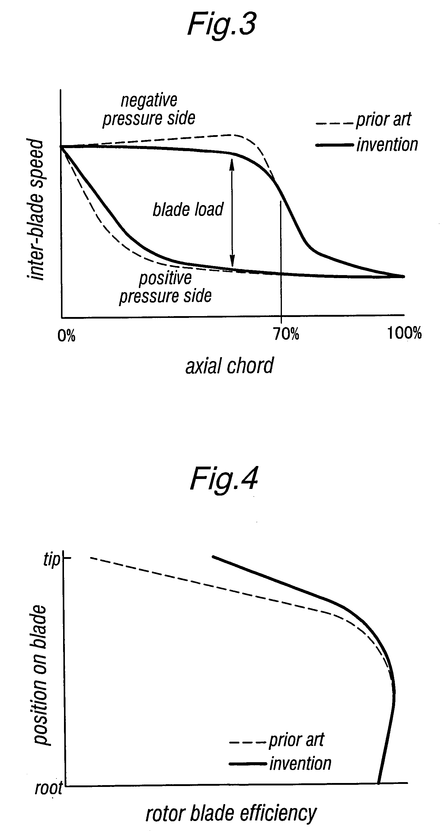
[0009]In particular, according to the present invention, the rotor blade efficiency can be improved over a wide operating range including a partial load condition, and the surge property can be improved significantly.

Problems solved by technology

The rotor blade of a transonic axial flow compressor (such as the one disclosed in U.S. Pat. No. 5,137,419) rotates at a high speed with a suitable gap defined between the tip of the blade and the opposing inner circumferential surface of the outer casing, and the region adjacent to the blade tip is subjected to an extremely complex flow pattern owing to the boundary layers that develop along the surfaces of the outer wall and the blade, the leak flow that flows through the gap defined between the blade tip and the opposing wall surface, and the interferences between these flows.
In particular, owing to the interferences between the leak flow produced in the gap between the blade tip and the opposing wall surface and the shockwave produced between adjacent rotor blades, a low momentum region having a certain circumferential expanse is produced behind a rear half of each rotor blade (see FIG. 5), and this not only severely impairs the efficiency of the tip end of each rotor blade but also degrades the surge property of the rotor blade.
Furthermore, the egress of such a low momentum region from each rotor blade promotes the development of a boundary layer on a downstream side of the rotor blade, and impairs the aerodynamic property of the stator blade located downstream of the rotor blade.
However, according to this prior proposal, a desired result may be achieved only over a certain operating range, but not outside this range because the compressive wave would not be produced as desired outside the limited operating range and hence the loss cannot be reduced to an acceptable extent.

Method used


Image

  • Axial flow compressor
  • Axial flow compressor
  • Axial flow compressor

Examples


Embodiment Construction

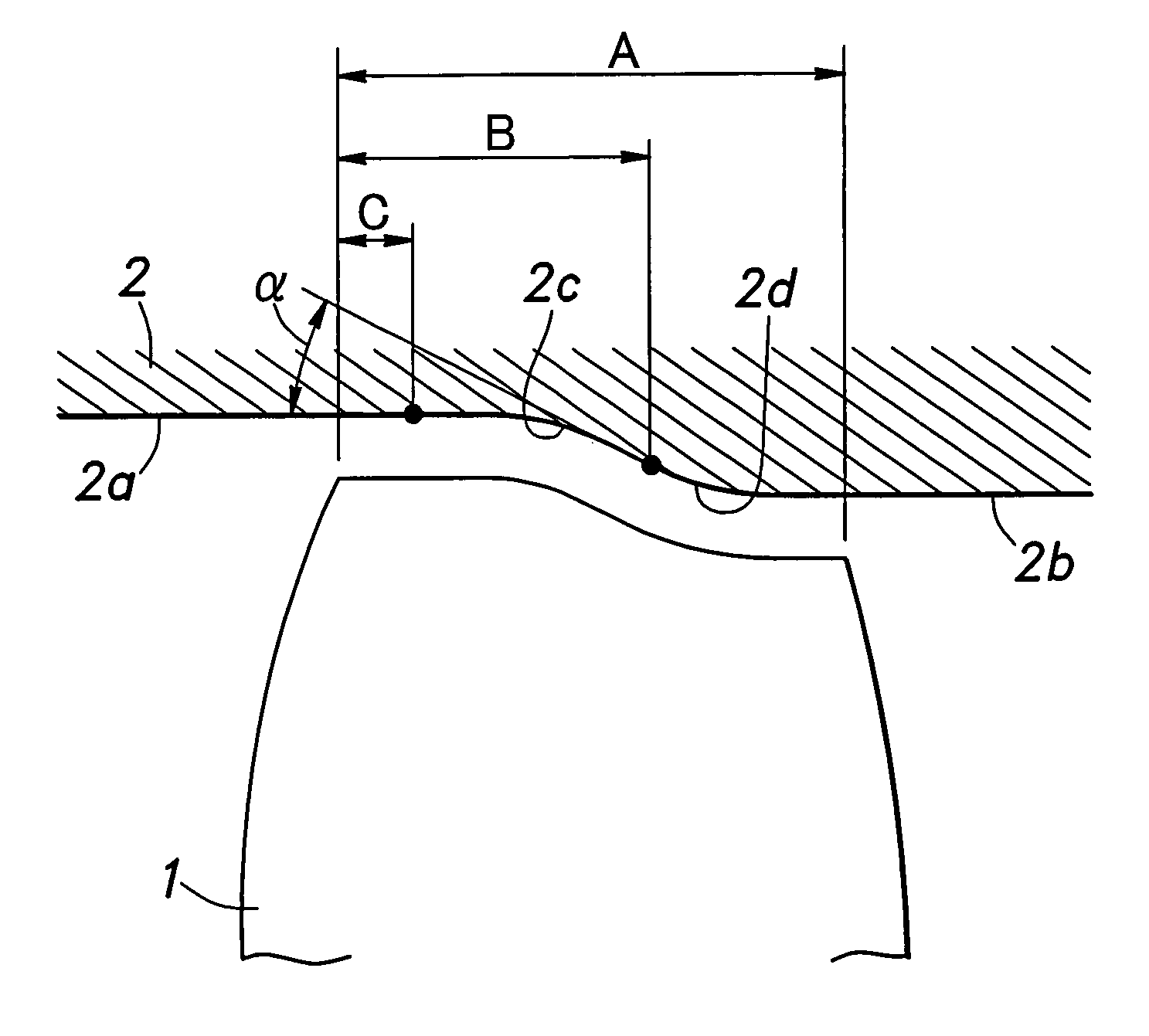
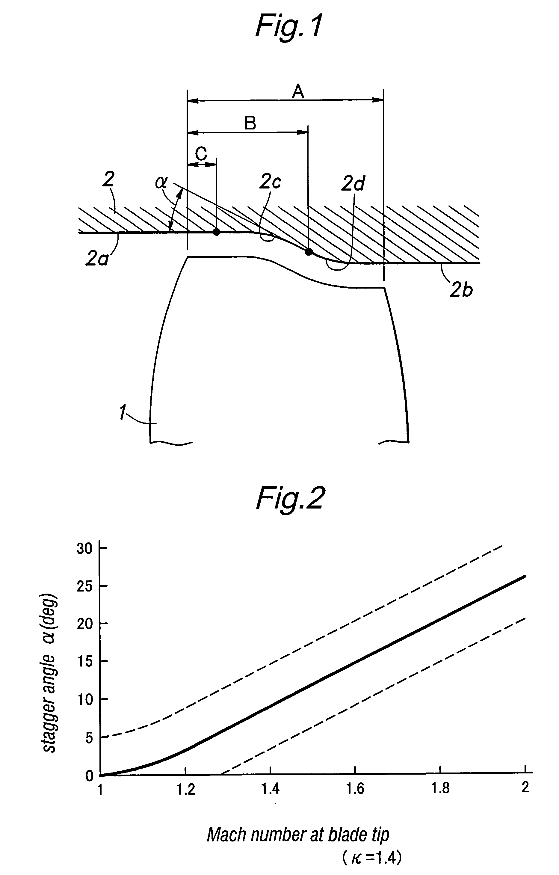
[0017]FIG. 1 is a diagram showing the relationship between an outer casing 2 and a rotor blade 1 of a transonic axial flow compressor when the relative Mach number of the airflow with respect to the tip of the rotor blade 1 and outer casing is 1.5. A certain gap is defined between the tip of the rotor blade 1 and the inner circumferential surface of the outer casing 2.

[0018]The cylindrical inner circumferential surface 2a of the outer casing 2 upstream of the leading edge of the rotor blade 1 is smoothly connected to the cylindrical inner circumferential surface 2b of the outer casing 2 downstream of the trailing edge of the rotor blade 1 by a curved surface having a substantially S-shaped longitudinal section. When the axial length A of the tip of the rotor blade 1 is given as a 100% axial chord length, this curved surface comprises a concave surface 2c (as seen in the longitudinal sectional view) consisting of a simple arc having a starting point located at a 20% chord position (a...


PUM


Abstract

At least part of the inner circumferential wall of the outer casing is provided with a concave surface opposing the rotor blade tips as seen in a longitudinal section. Typically, each of the rotor blades is provided with aerofoil section, and the compressor is designed as a transonic axial flow compressor. Thereby, a compressive wave is produced upstream of the shockwave so that the Mach number of the flow entering the shockwave can be reduced. As a result, the shockwave is made less severe, and the shockwave loss can be reduced. In particular, because the concave surface is provided in the casing wall as opposed to the case where the concave surface is provided in the negative pressure side of the rotor blade, the reduction in the performance owing to the change in the angle of the airflow entering the passage defined by the concave surface under a partial load condition can be avoided.

Description

TECHNICAL FIELD[0001]The present invention relates to an axial flow compressor that is typically but not exclusively used in gas turbine engines.BACKGROUND OF THE INVENTION[0002]The rotor blade of a transonic axial flow compressor (such as the one disclosed in U.S. Pat. No. 5,137,419) rotates at a high speed with a suitable gap defined between the tip of the blade and the opposing inner circumferential surface of the outer casing, and the region adjacent to the blade tip is subjected to an extremely complex flow pattern owing to the boundary layers that develop along the surfaces of the outer wall and the blade, the leak flow that flows through the gap defined between the blade tip and the opposing wall surface, and the interferences between these flows. In particular, owing to the interferences between the leak flow produced in the gap between the blade tip and the opposing wall surface and the shockwave produced between adjacent rotor blades, a low momentum region having a certain...

Claims


Application Information

Patent Timeline
Patent Type & Authority Patents(United States)
IPC IPC(8): F01D5/20F01D5/14F04D21/00F04D29/54F04D29/68
CPCF01D5/143F01D5/20F04D29/681F04D29/545F04D21/00
Inventor TERAMURA, MINORUTAKADO, JUNJIHOSHINO, GENSUKE
Owner HONDA MOTOR CO LTD
Why Eureka
Try Eureka