Method for flat electrodes

a flat electrode and electrode technology, applied in the manufacture of electrode systems, electrical discharge tubes/lamps, electrical apparatus, etc., can solve the problems of limited use of such electrodes in tunneling diodes, and achieve the effect of promoting preferential evaporation and reducing nanoscale roughness on a surfa

Inactive Publication Date: 2006-02-28
BOREALIS TECH LTD
View PDF3 Cites 14 Cited by
  • Summary
  • Abstract
  • Description
  • Claims
  • Application Information

AI Technical Summary

Benefits of technology

[0006]The present invention is a method for reducing nanoscale roughness on a surface. The method comprises exposing a surface t

Problems solved by technology

Using such a pair of electrodes in a tunneling diode device may be limited by nanoscale roughness; peaks, ridges, etc in one electrode that have dimensio

Method used


Image

  • Method for flat electrodes
  • Method for flat electrodes
  • Method for flat electrodes

Examples


Embodiment Construction

[0017]The embodiments of the present invention and its technical advantages are best understood by referring to FIGS. 1–5.

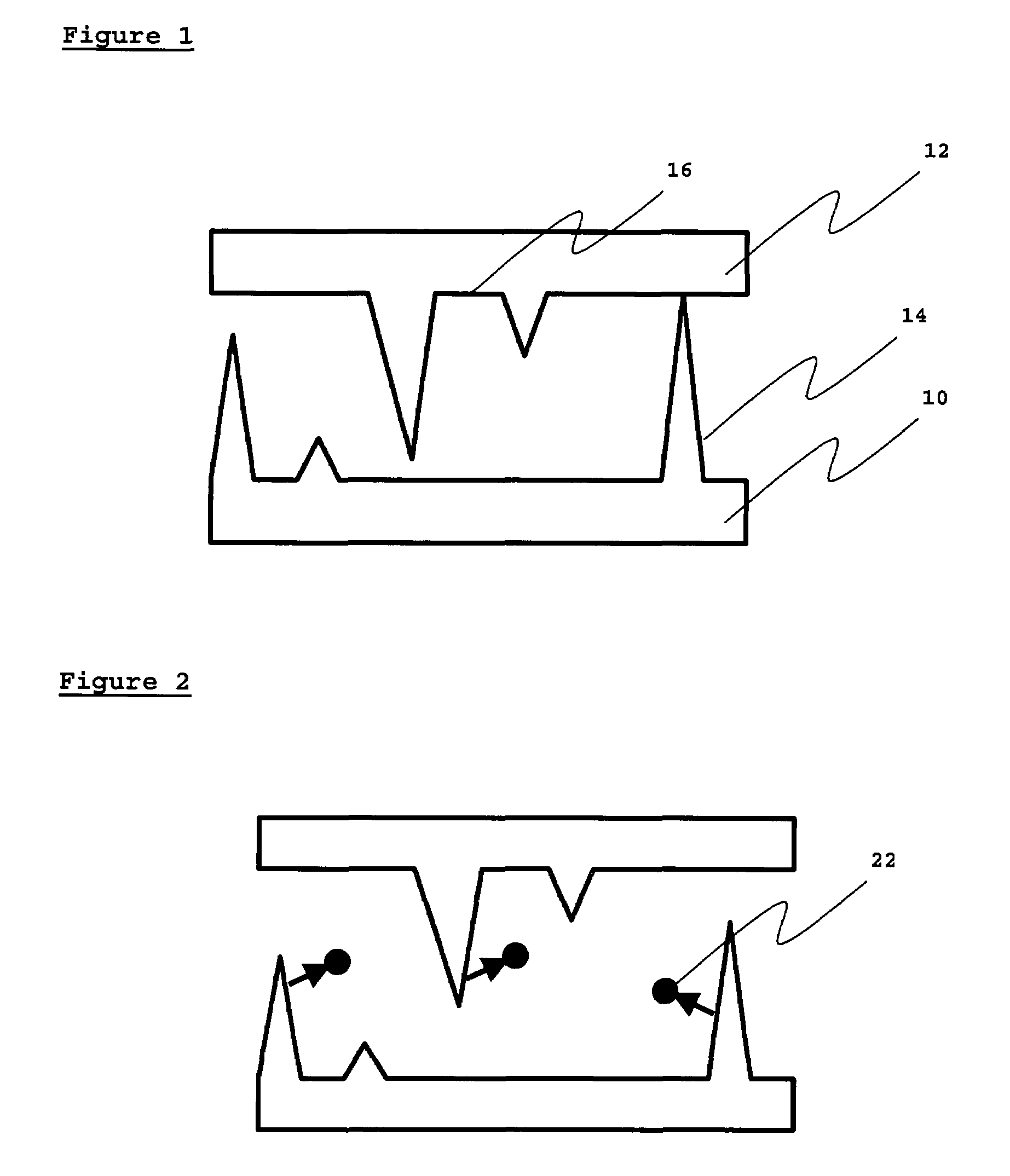
[0018]The present invention is a method for reducing nanoscale surface roughness from the surface of an electrode. FIG. 1 shows a greatly enlarged schematic of nanoscale roughness on the surface of electrodes 100 and 102, and shows how peak areas 104 prevent flat areas 106 from coming into close proximity.

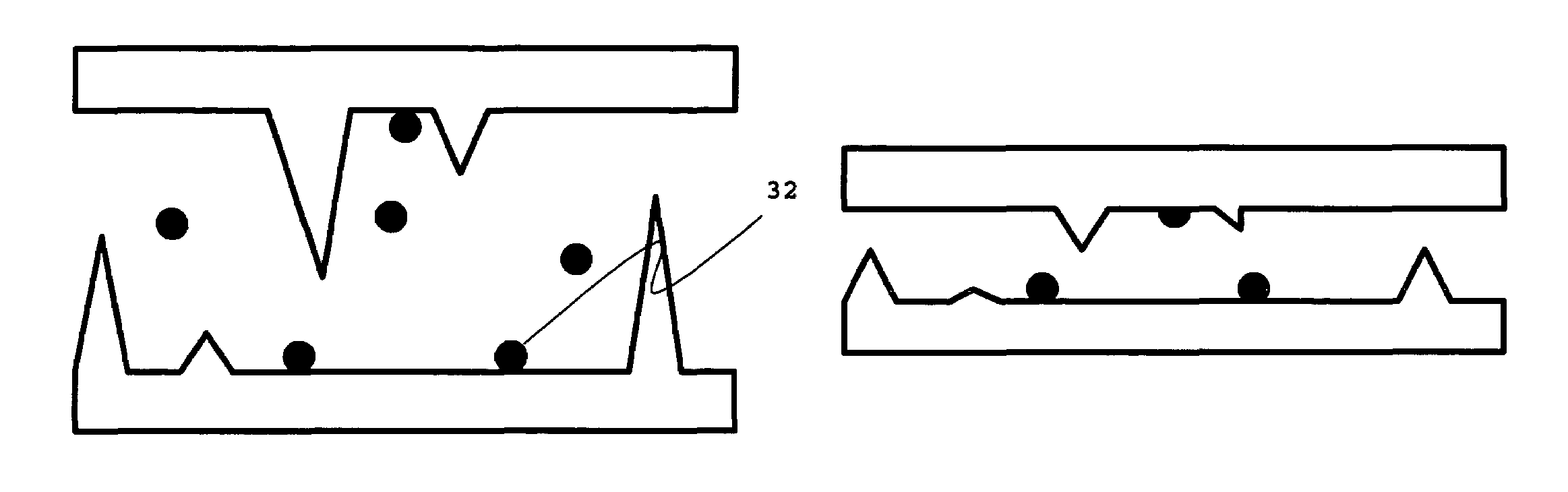
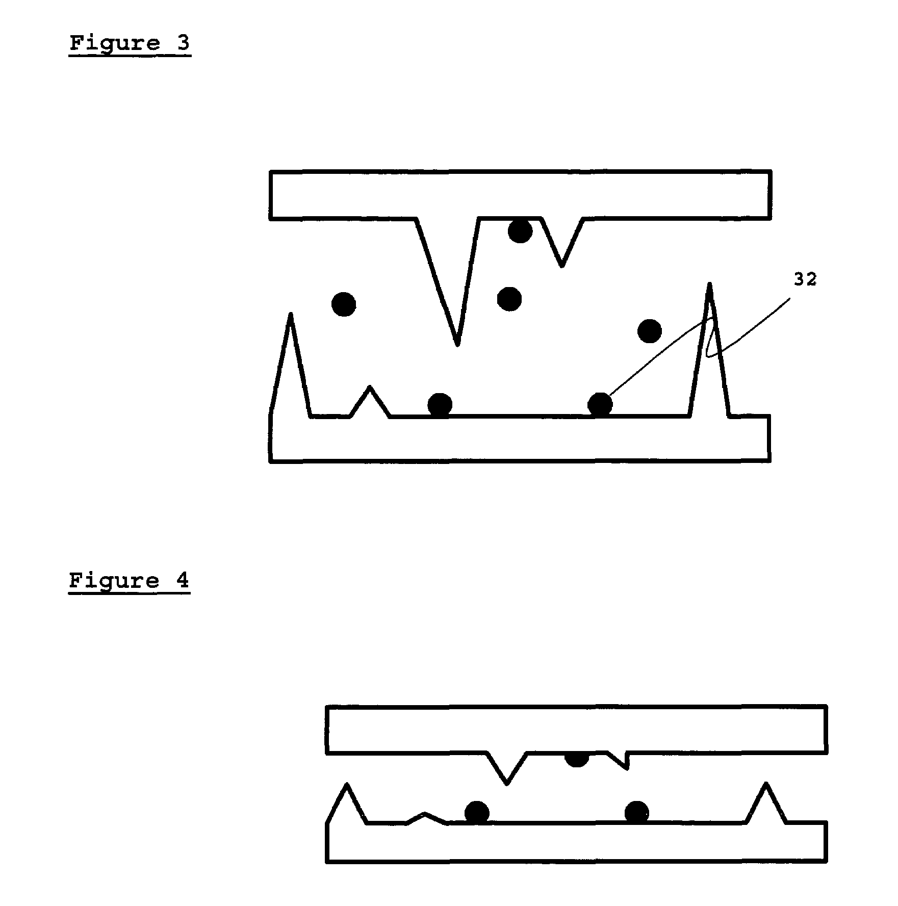
[0019]The method of the present invention comprises the placing of a surface having nanoscale roughness, such as an electrode or an electrode pair, in an environment where evaporation from the peak areas 104 is enhanced in comparison to evaporation from flat areas 106. This process may be better understood by referring to FIG. 2, where atoms 108 are shown leaving the peak areas 104. This loss of material results in the depletion of the peak areas, and a reduction in nanoscale roughness, as shown in FIG. 3.

[0020]FIG. 3 also shows what happens to the atoms, 110, w...


PUM


Abstract

The present invention is a method for reducing nanoscale surface roughness. The method involves exposing the surface to an environment that preferentially promotes evaporation of material from the region of nanoscale roughness. The methods involve either heating the surface, or flushing an inert gas across the surface, or a combination of both.

Description

CROSS-REFERENCE TO RELATED APPLICATIONS[0001]This application claims the benefit of U.S. Provisional Application No. 60 / 403,092, filed 12 Aug. 2002.BACKGROUND OF THE INVENTION[0002]For tunneling diode devices, the separation of the electrodes is necessarily very small (<1–10 nm) so that electrons may tunnel from an emitter electrode to a collector electrode. Performance of such a device is very dependent on creating and maintaining a gap having such small dimensions.[0003]In U.S. Pat. No. 6,417,060 Tavkhelidze et al. disclose a method for manufacturing a pair of electrodes in which topological features in one electrode are matched in the other. The method involves fabricating a first electrode with a substantially flat surface and placing a sacrificial layer over it. A further material is placed over the sacrificial layer. The sacrificial layer is removed with an etchant. Alternatively, the sacrificial layer is removed by cooling the sandwich with liquid nitrogen, or alternativel...

Claims


Application Information

Patent Timeline
IPC IPC(8): H01L21/302
CPCH01J9/02H01J21/04H01L37/00H10N15/00
Inventor COX, ISAIAH WATAS
Owner BOREALIS TECH LTD
Why Eureka
Try Eureka